|
|
 |
|
Sparker discharge begins the show, 3 torr pressure in air, loaded with flour and graphite powder
|
|
 |
|
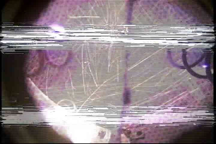
After sparker discharge is over (drat, will be simultaneous later) microwave breakdown starts at base of antennas
|
|
 |
|
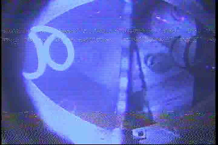
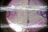
Peak of microwave discharge (left out a couple of frames)
|
|
 |
|
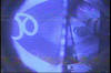
End of discharge, dying away; starts and ends at base of antennas
|
|
 |
|
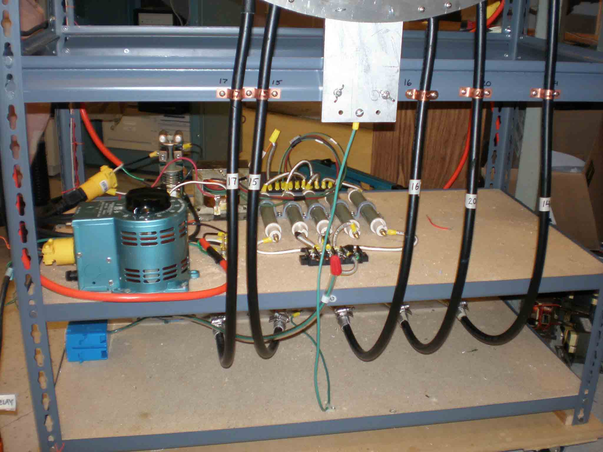
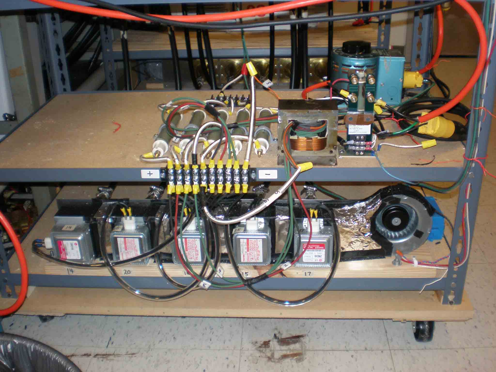
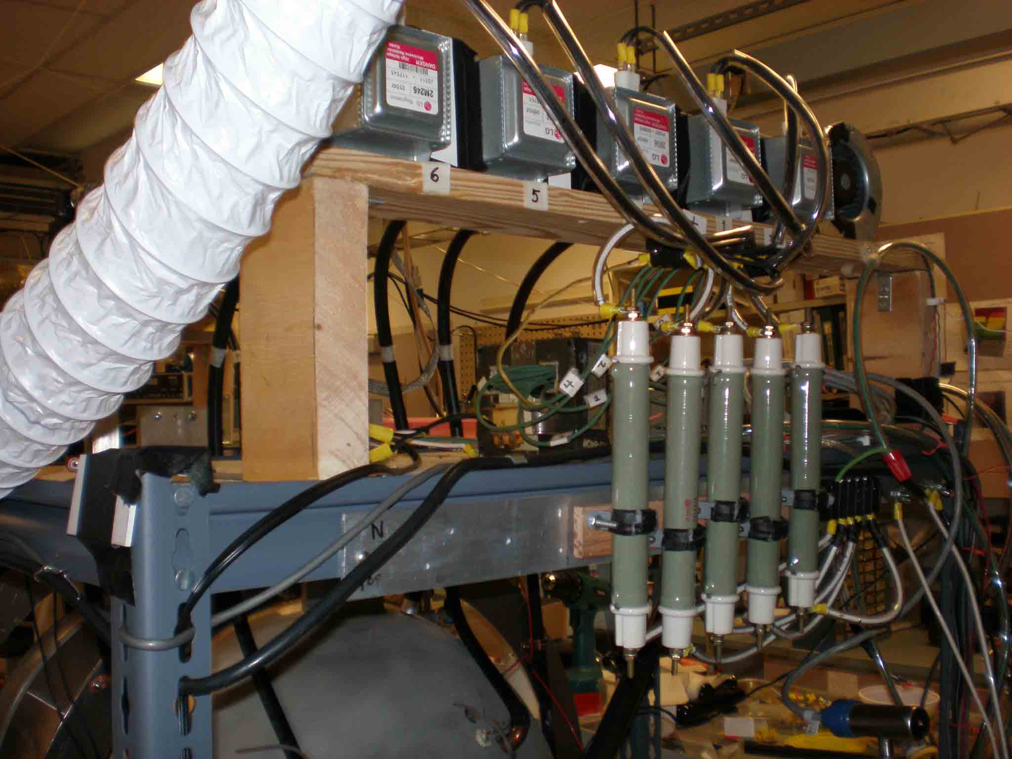
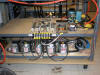
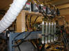
New arrangement of wiring and power distribution; see big new resistors (small older ones blew up), 500 ohms distribute current pulse among magnetrons; variac adjusts power to magnetron filaments (3VAC after another transformer)
|
|
|
|
 |
|
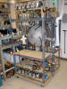
South bottom in back
|
|
 |
|
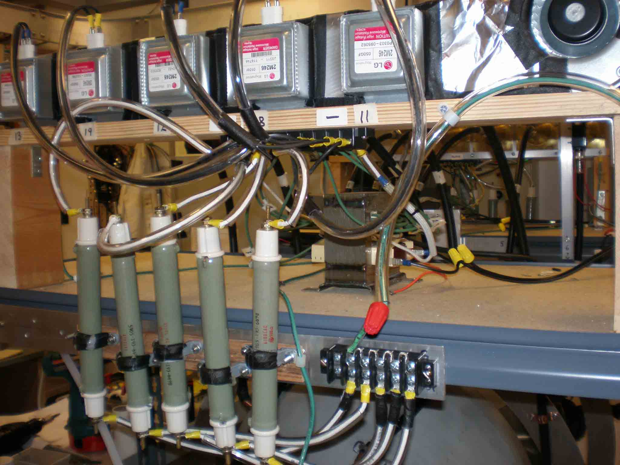
South top in back; resistors vertical (from an old accelerator)
|
|
 |
|
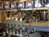
South top front. See old oven transformer I re-wound with new 3 V secondaries, wire insulated to 5000 V to take the big pulse from the cap bank
|
|
 |
|
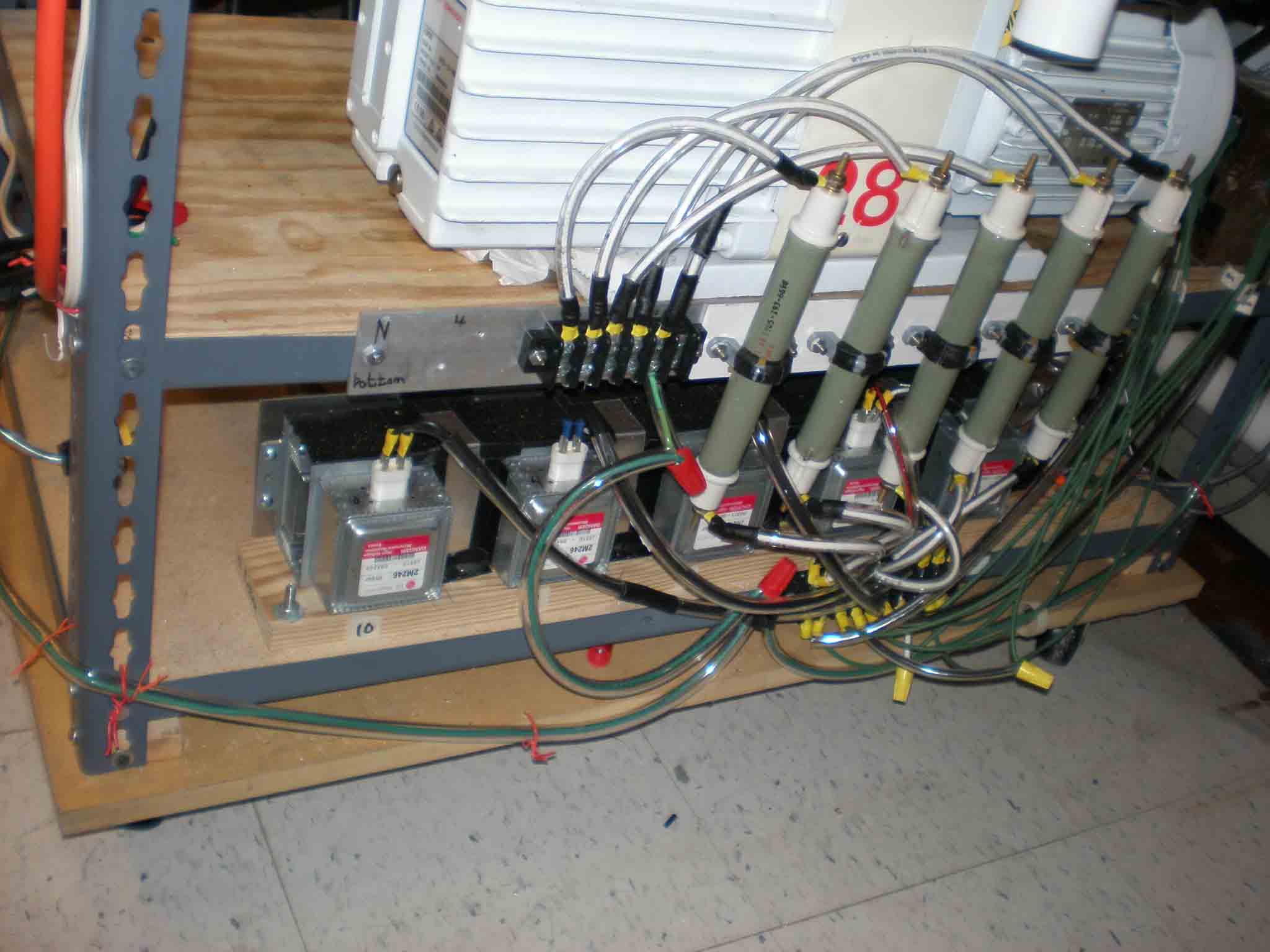
North bottom in back
|
|
 |
|
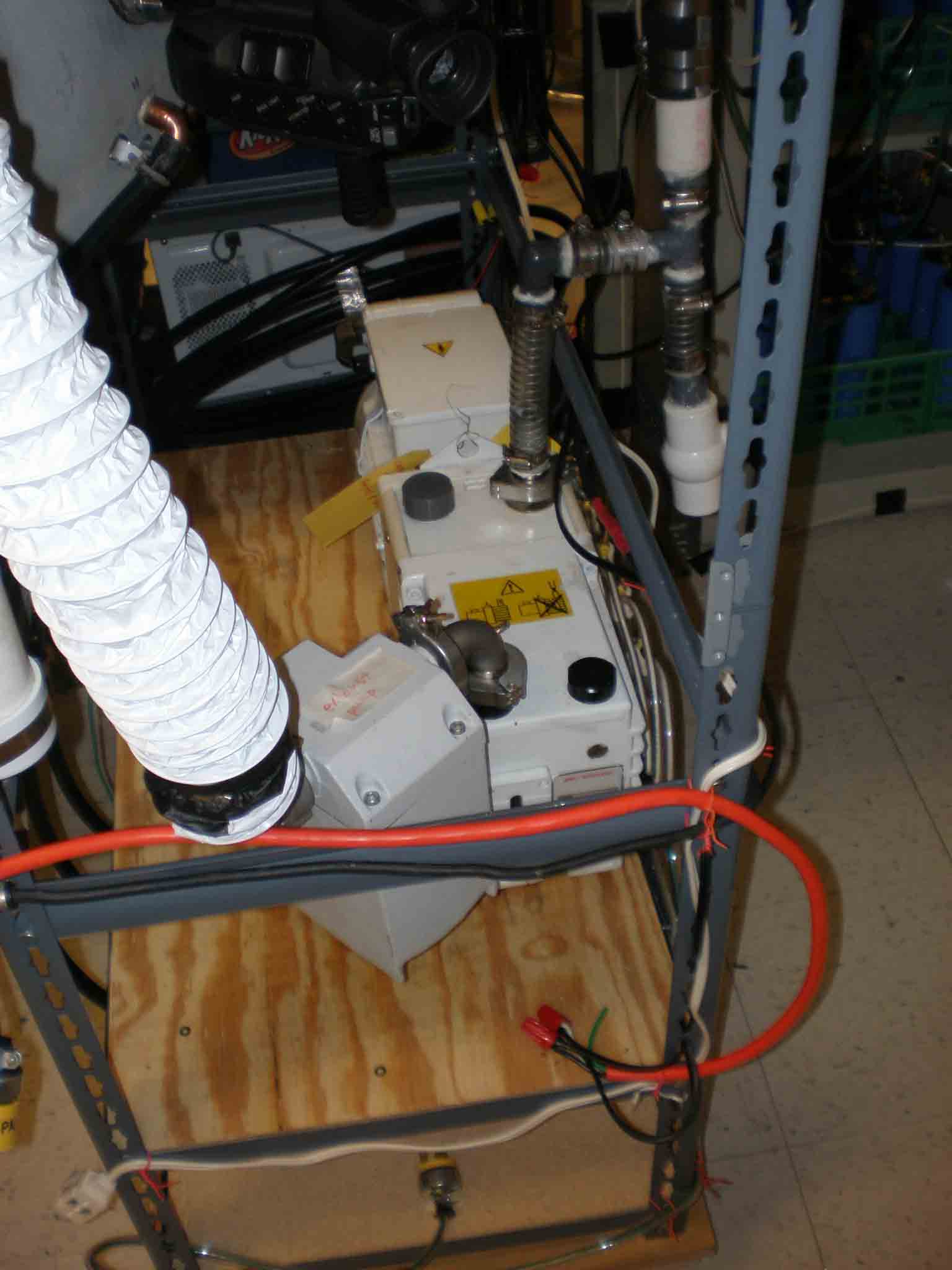
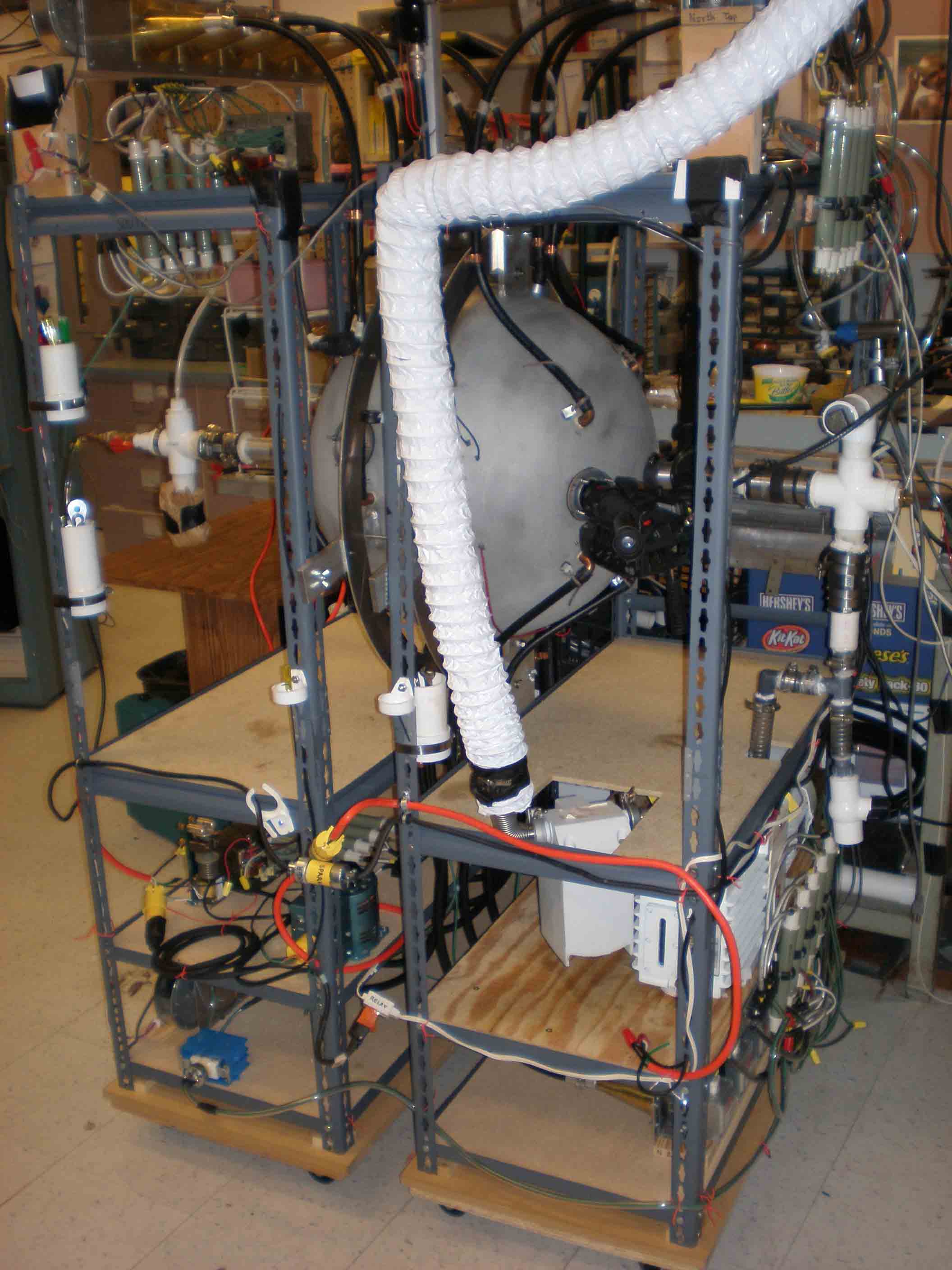
Pump with exhaust pipe (to the roof)
|
|
|
|
 |
|
N top in back, vertical resistors
|
|
 |
|
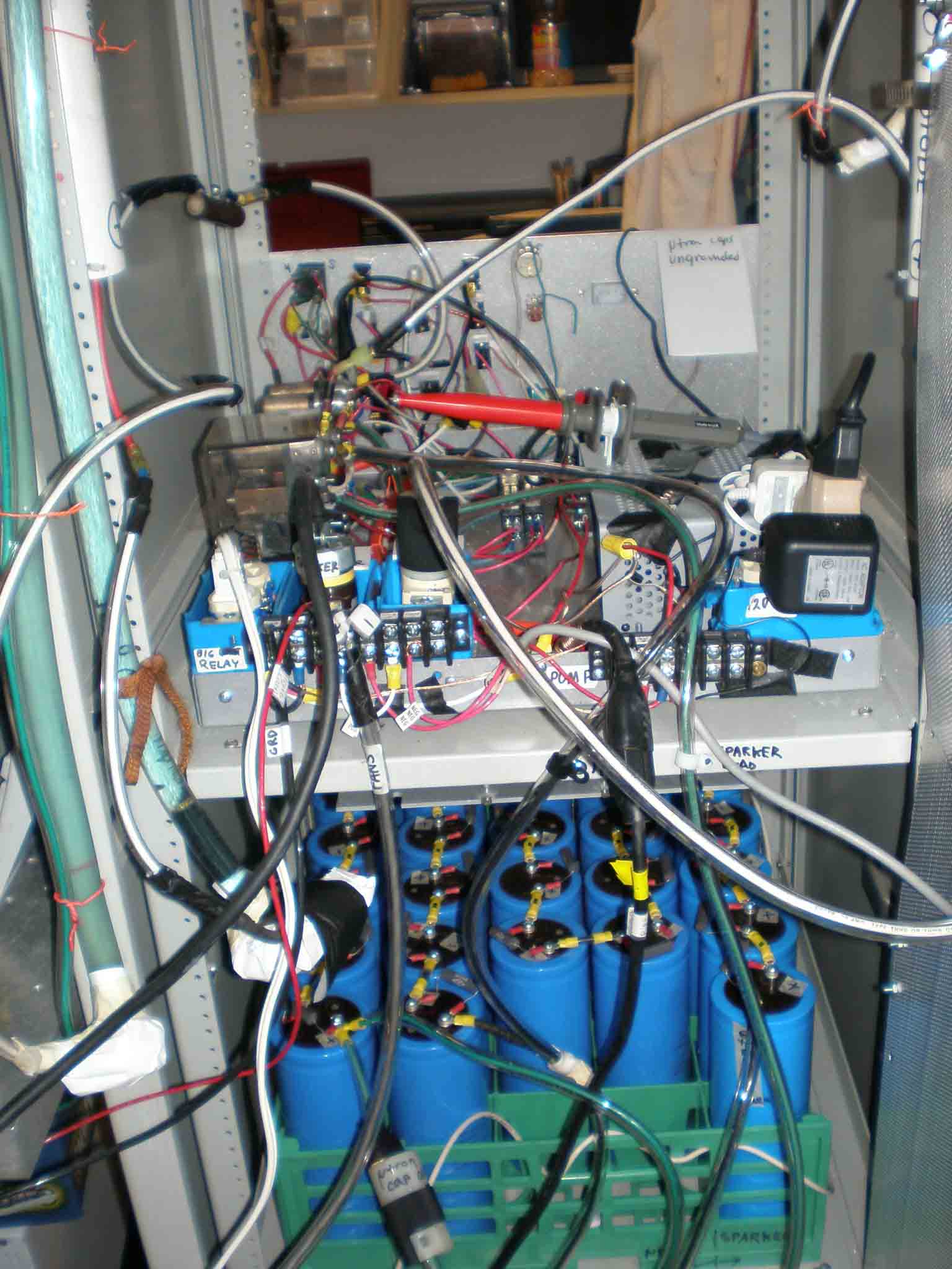
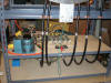
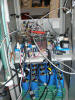
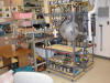
Rack showing back of control panel and top tray of capacitors (of two trays)
|
|
 |
|
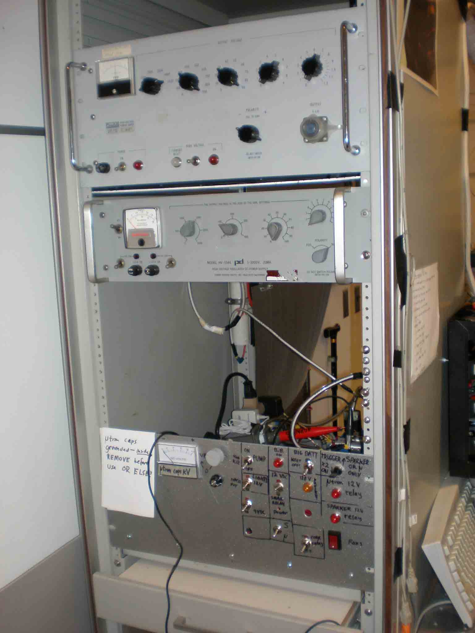
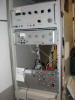
Front of rack; Fluke 6000 VDC power supply on top, then 2000 VDC power supply, then control panel
|
|
 |
|
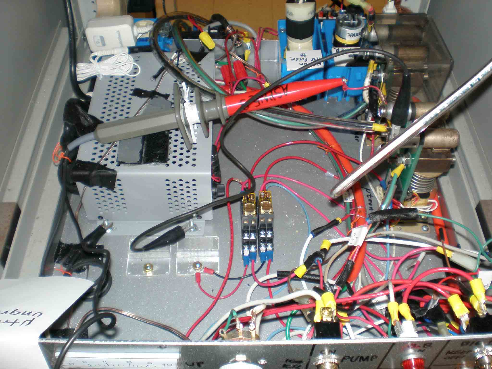
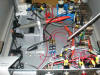
Close up behind control panel
|
|
 |
|
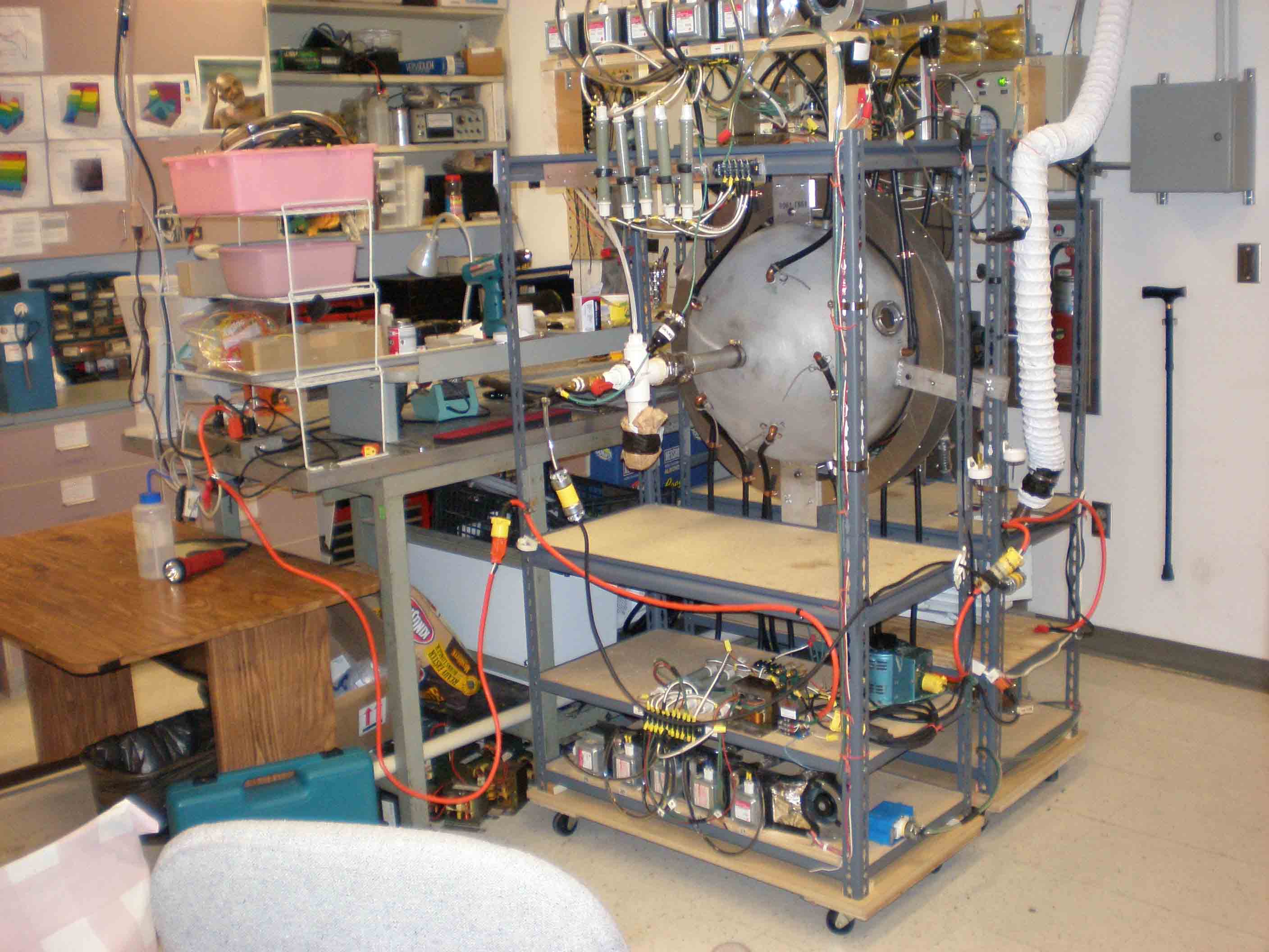
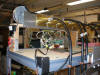
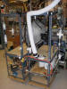
Assembled ready to fire from north corner
|
|
|
|
 |
|
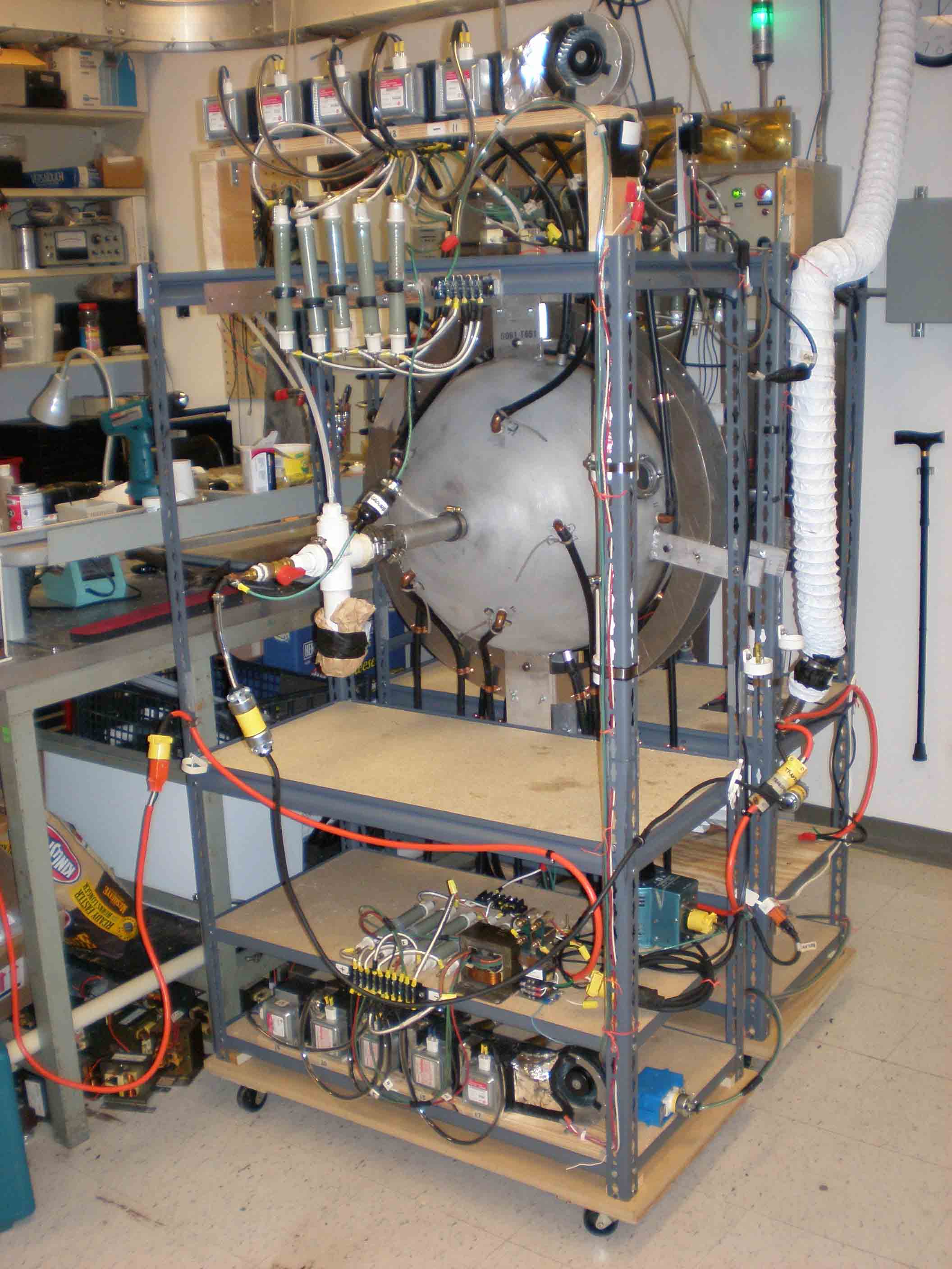
Ready to fire from south corner
|
|
 |
|
Closer assembled from south
|
|
 |
|
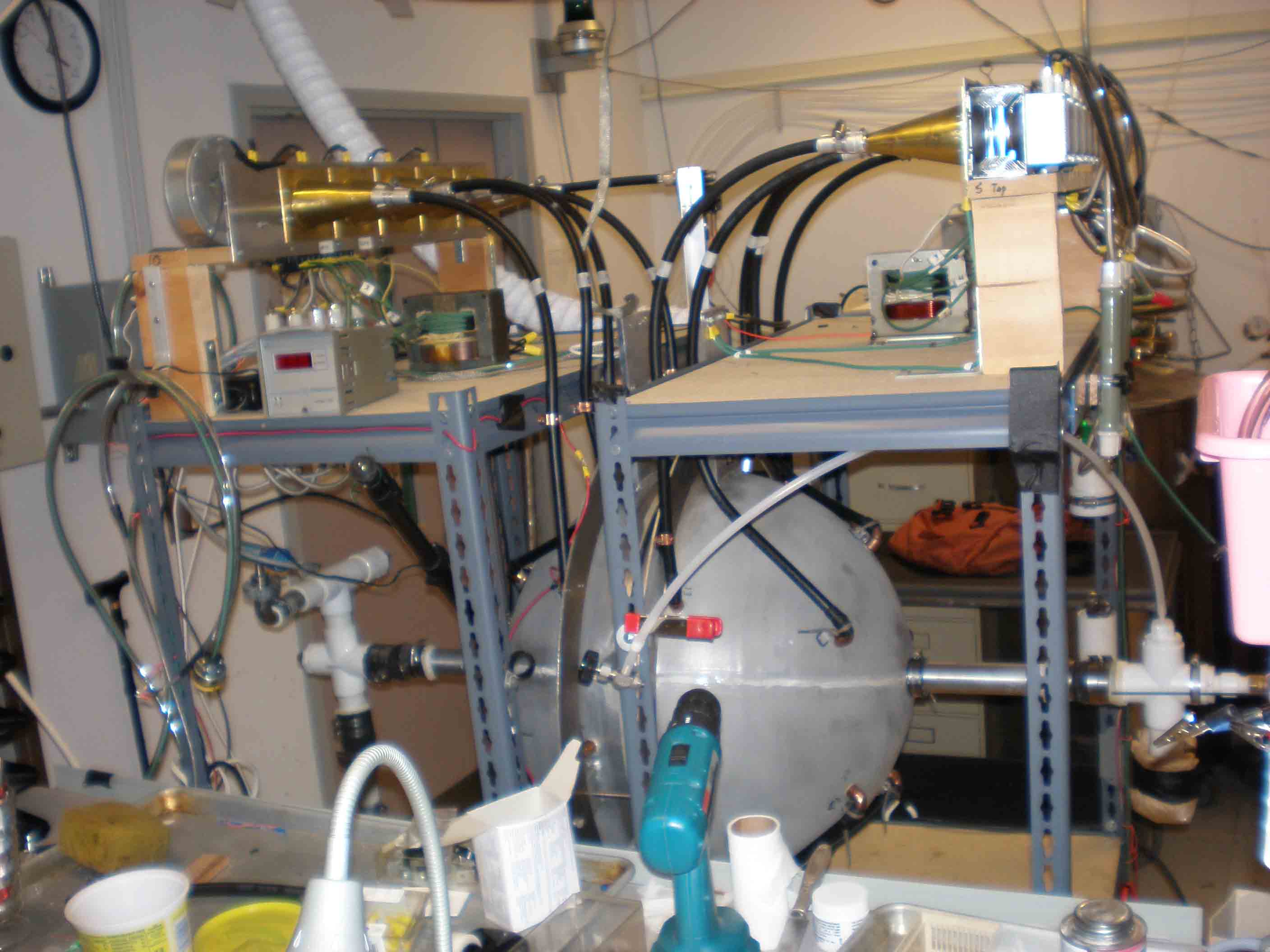
From across the desk ready to go
|
|
 |
|
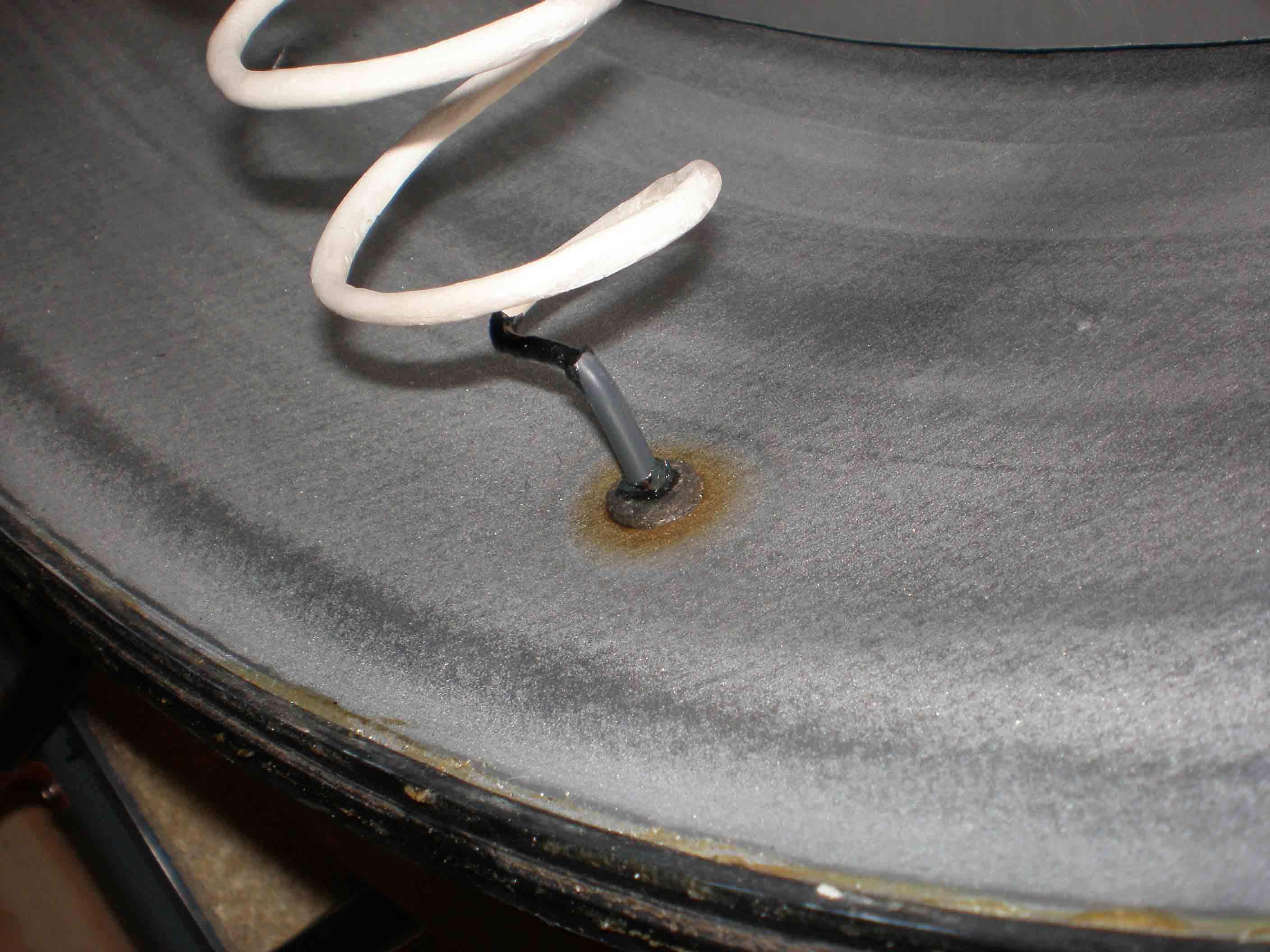
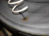
Damage (scorch marks) at base of antenna after operating at atmospheric pressure. Was bare copper at base then, shown here after adding rubber insulation
|
|
 |
|
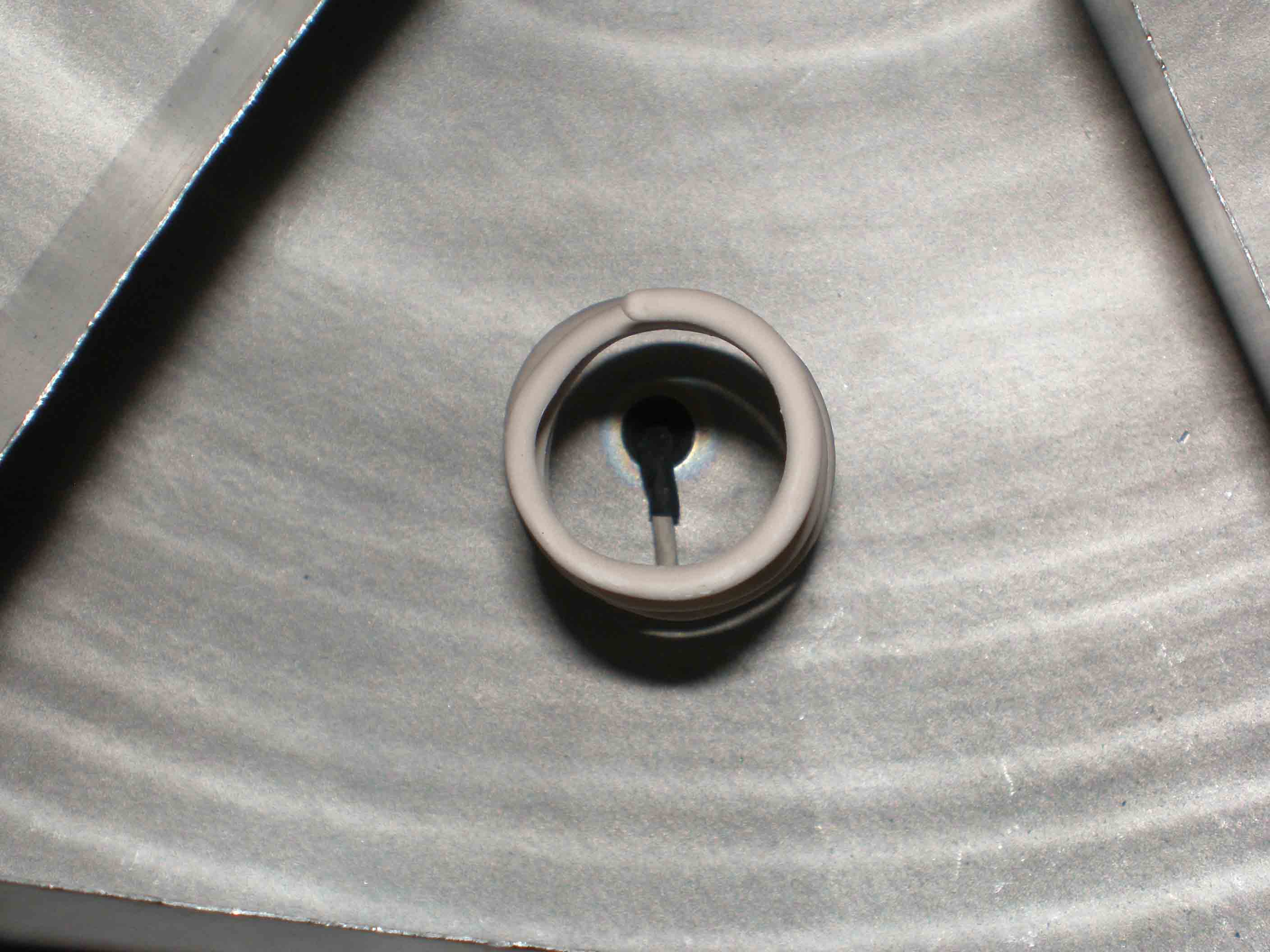
Antenna from center of sphere showing some burn marks at base
|
|
|
|
 |
|
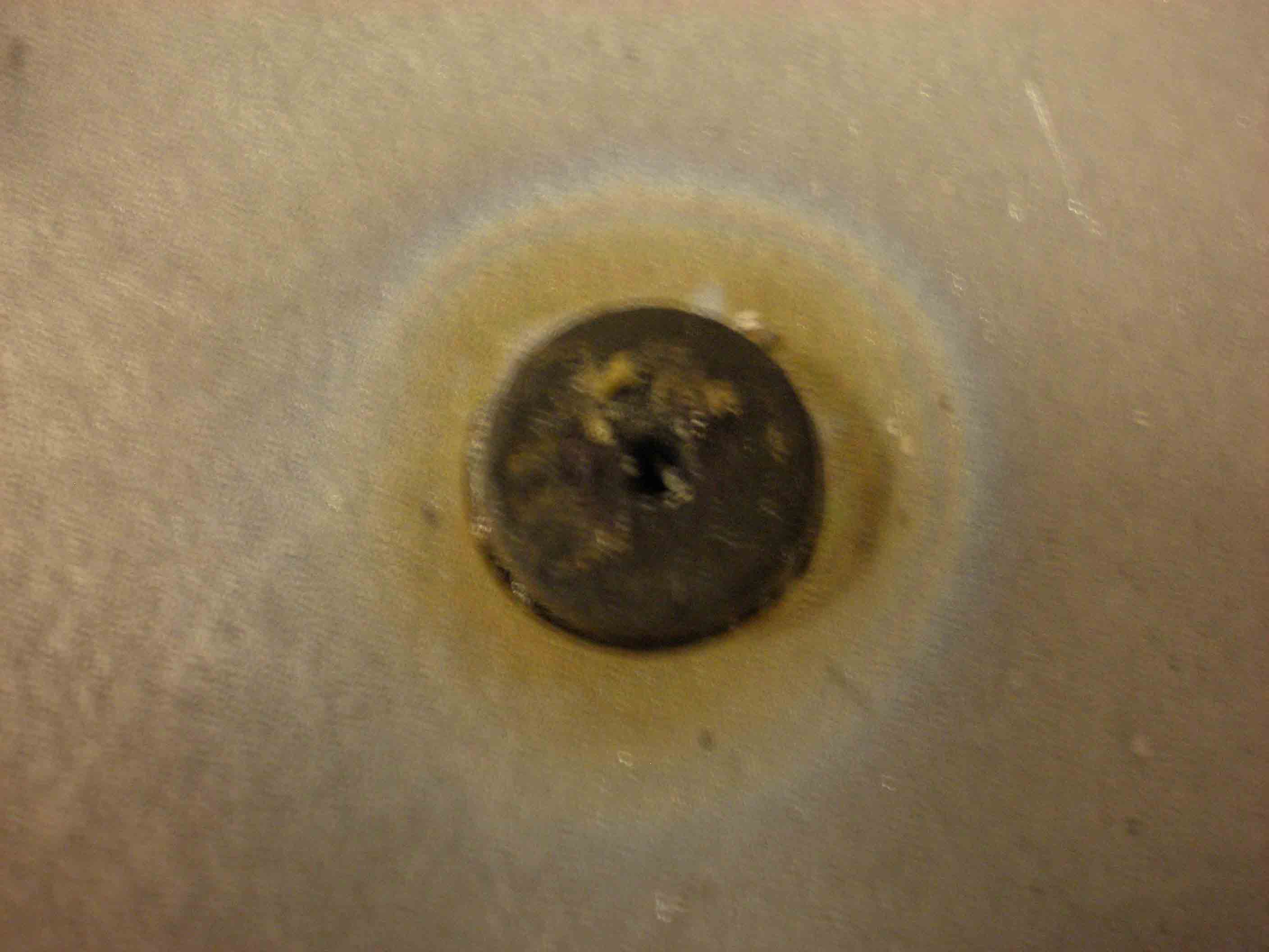
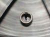
Plug damage
|
|
 |
|
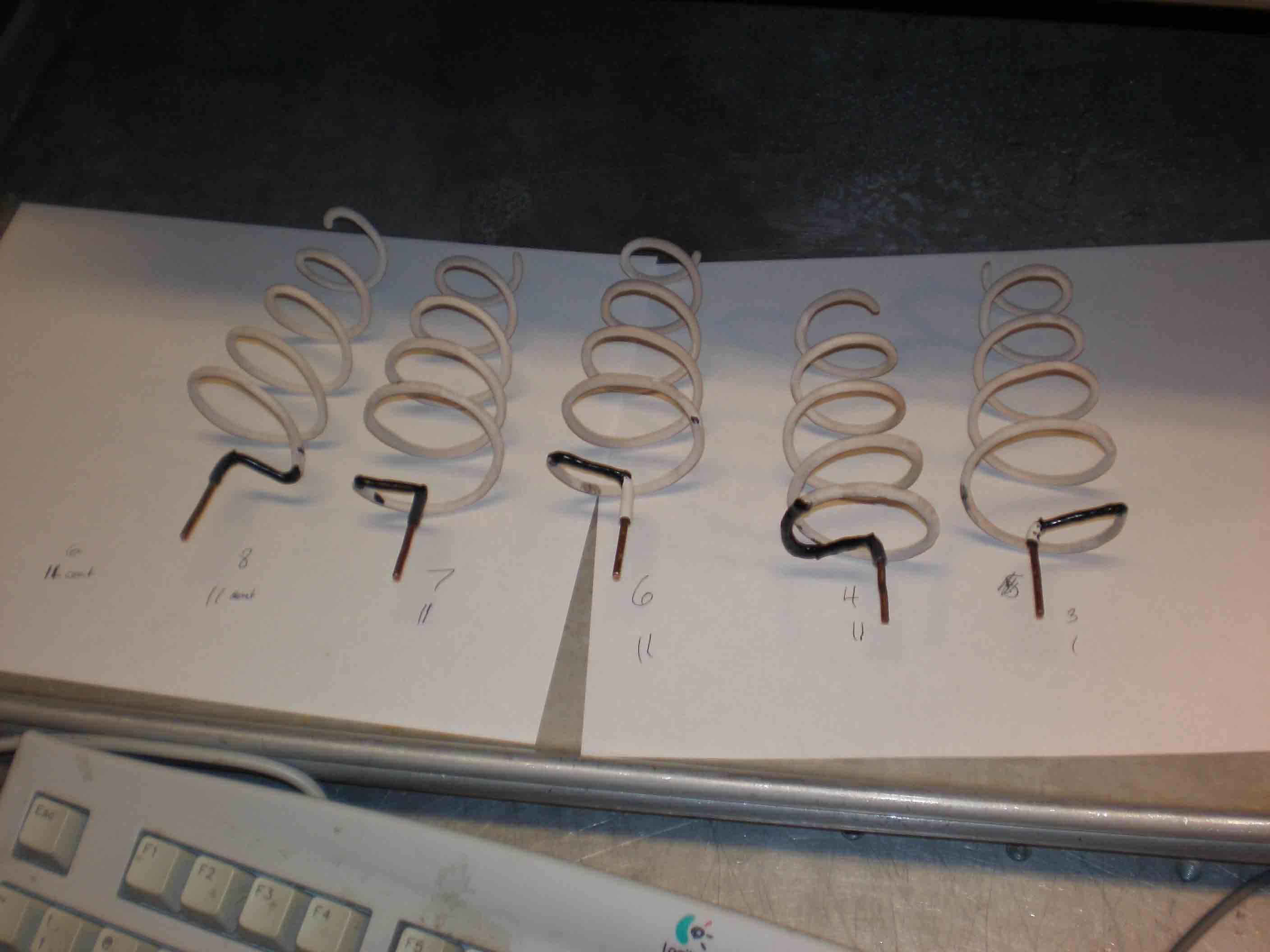
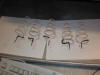
Insulating the bases of antennas with rubber paint, rubber tape, and shrink tubing
|
|
 |
|
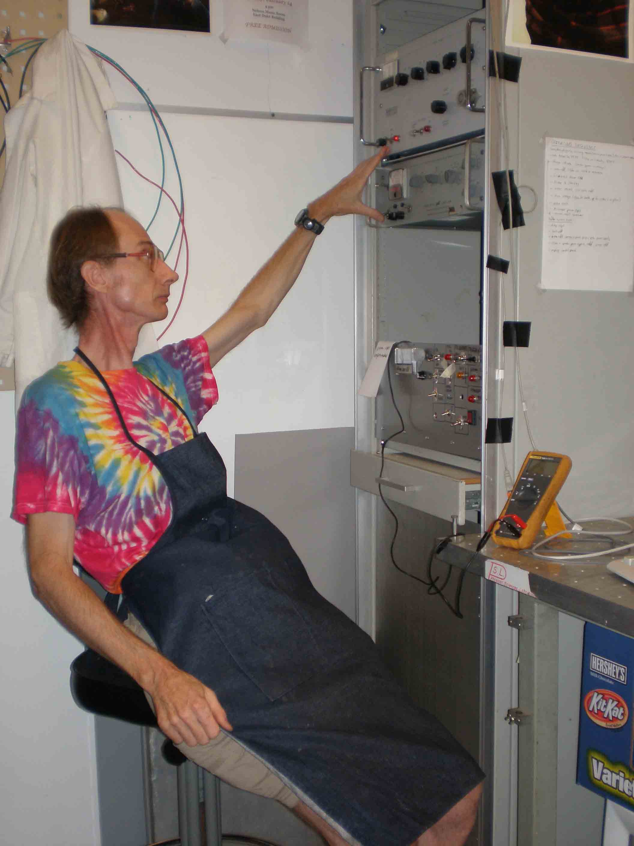
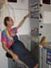
Me running the reactor
|
|
|
 Lab Pictures 4