 Lab Pictures 9
January 1, 2009; Room 102-A, Research II
NCSU, Raleigh NC
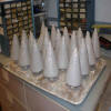
At the end of September, the new Mark II antennas had the epoxy core (with its embedded conical helix of copper wire) coated with silica ceramic composite, over which is a shield of copper sheet metal triangles and a sturdy base of copper sheet metal and copper pipe. This pipe is brazed onto a brass bushing that screws into the wall of the reactor.
The outer shield, in turn, needs to be coated with more ceramic for two reasons. First, without such a shield, the discharge is lumpy, forming mostly over the gaps between the triangles; but with a 1/8 inch layer of ceramic, the discharge is mostly quite smooth over the cone at the operational pressures (have tested down to 120 mtorr). Second, there needs to be a current between the outer grid rings and the inner tips of the shield, so everything is coated with ceramic except for these tips. Note that the final antenna photos here show total coverage, but that is after dipping in boron nitride paint, and later I take the paint off the shield tips.
The silica ceramic works well and doesn't need firing, which is critical; however it powders easily and creates dust in the plasma. Also the clay ceramic coating of the inner wall of the sphere creates dust as well, which would wreck the turbo pump in addition to ruining the plasma. So at the end of this gallery I show spray painting the sphere as well; however the earlier layers of clay did not adhere well enough to itself to withstand the slight shrinkage of this hard BN paint, and so afterwards I had to take it all off down to the metal and spray with BN paint, shown in the next gallery.
|
|
 |
|
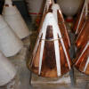
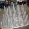
Putting ceramic over the shields
Without the ceramic, the current from the grids goes directly to the bases instead of to the tips, and the microwave discharge is lumpy instead of smooth
|
|
 |
|
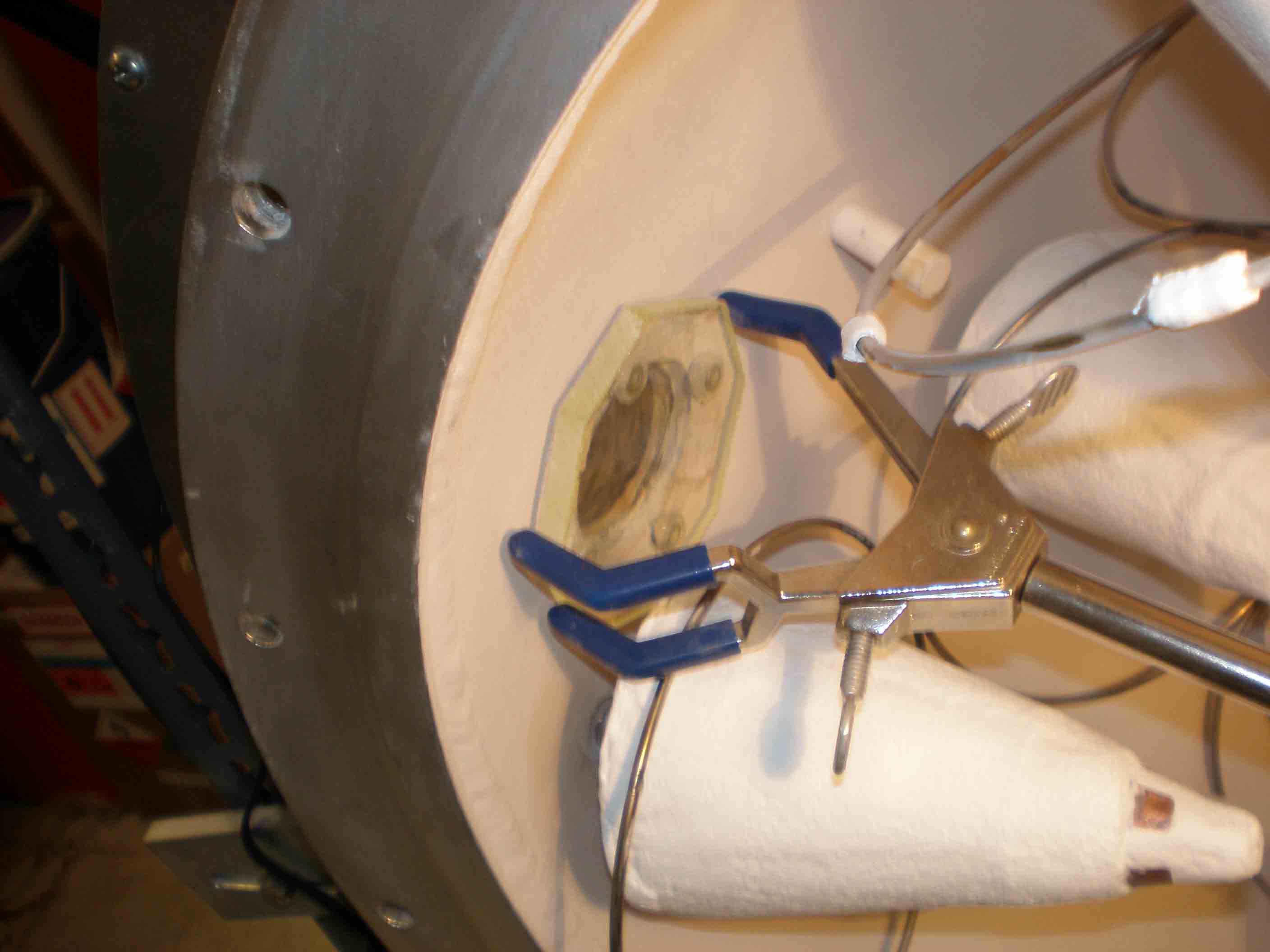
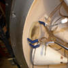
Close-up shield
Shows retaining wire ring, solder joints. The small triangles are entirely covered later with ceramic, leaving the four truncated tips bare
|
|
 |
|
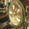
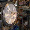
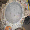
North hemisphere mounted with grid
The new Mark II antennas are too big to put the grid in after the antennas so the grid has to go in first on its 1" ceramic mounts.
|
|
 |
|
North Hemisphere, no flash
|
|
 |
|
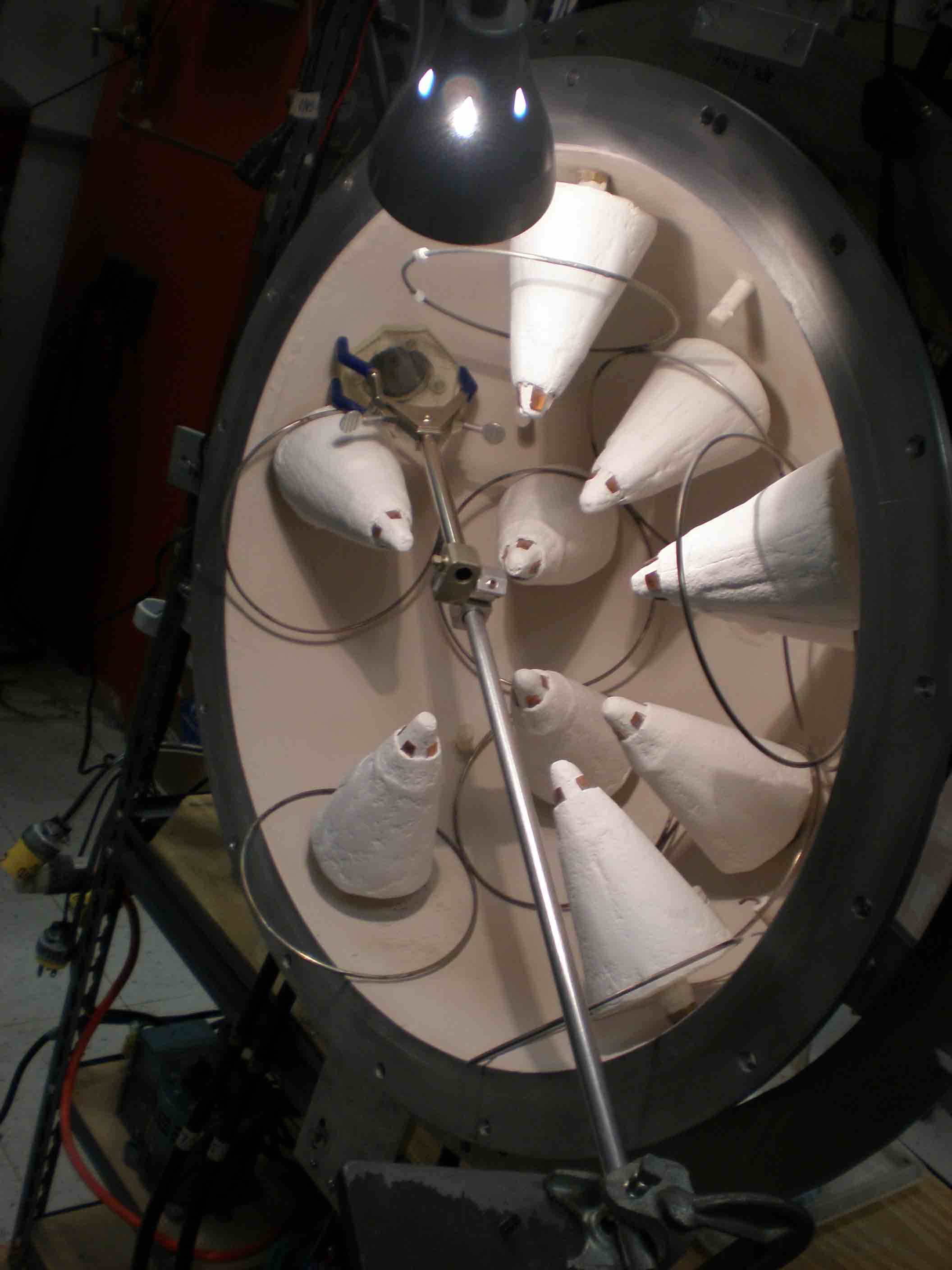
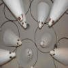
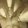
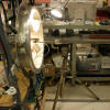
Mounted antennas and grid
|
|
|
|
 |
|
Mounted antennas and grid, no flash
|
|
 |
|
Mounting lead glass
To shield from x-rays, I'm using thick lead glass. This early mounting technique glued them onto the window bolts
|
|
 |
|
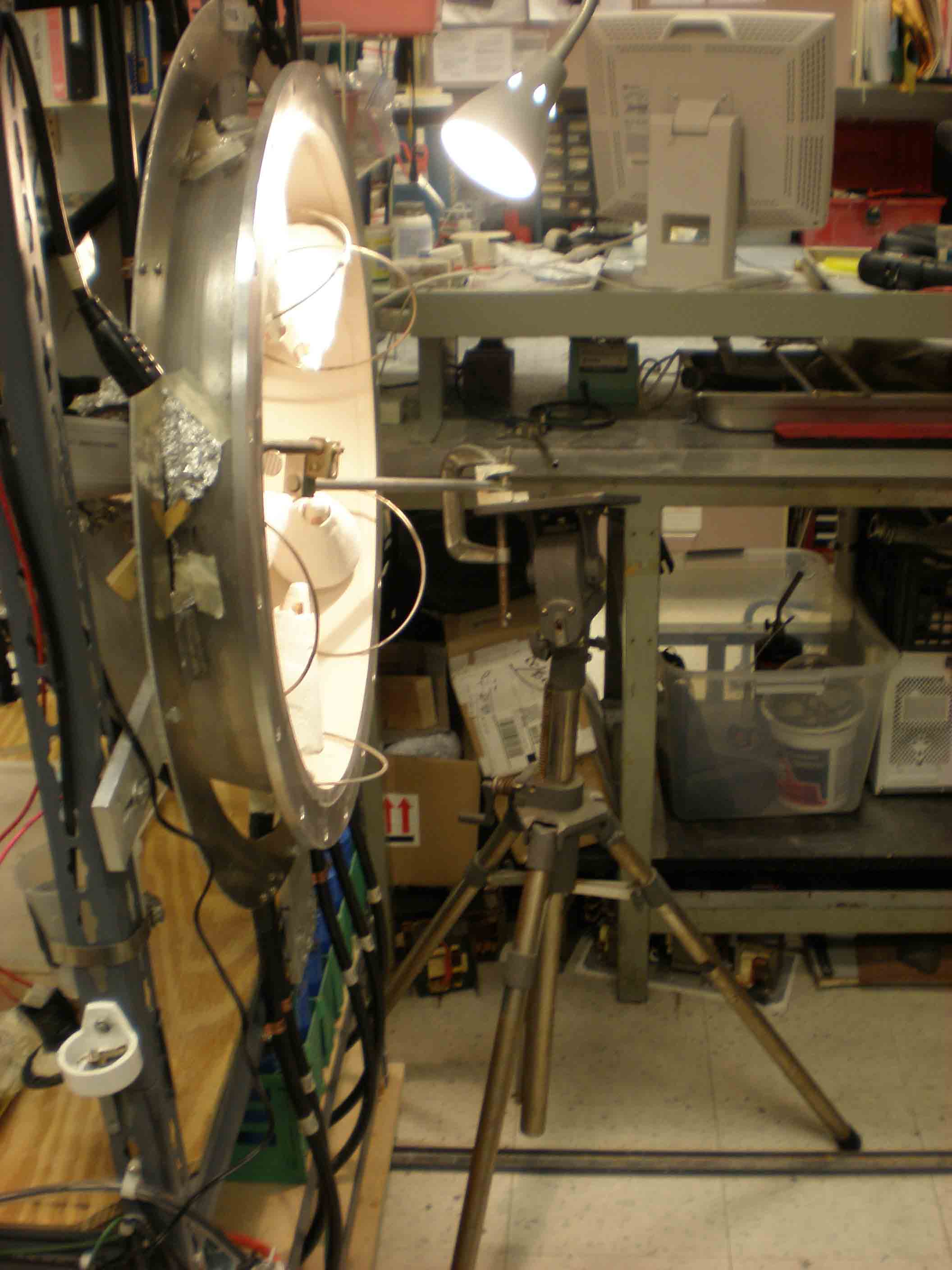
Mounting lead glass
This required a tripod and some fancy bracing to hold until the silicone adhesive dried
|
|
 |
|
Mounting lead glass
However I now cut the glass smaller and fit it directly into the hole in the metal wall, makes it removable and cleanable
|
|
 |
|
Mounting lead glass
|
|
|
|
 |
|
Mounting lead glass, early method
|
|
|
 |
|
Mounting lead glass
|
|
 |
|
Gallon of Boron Nitride paint
The silica ceramic has a powdery surface that must be hardened to prevent contamination of the plasma and gas
|
|
 |
|
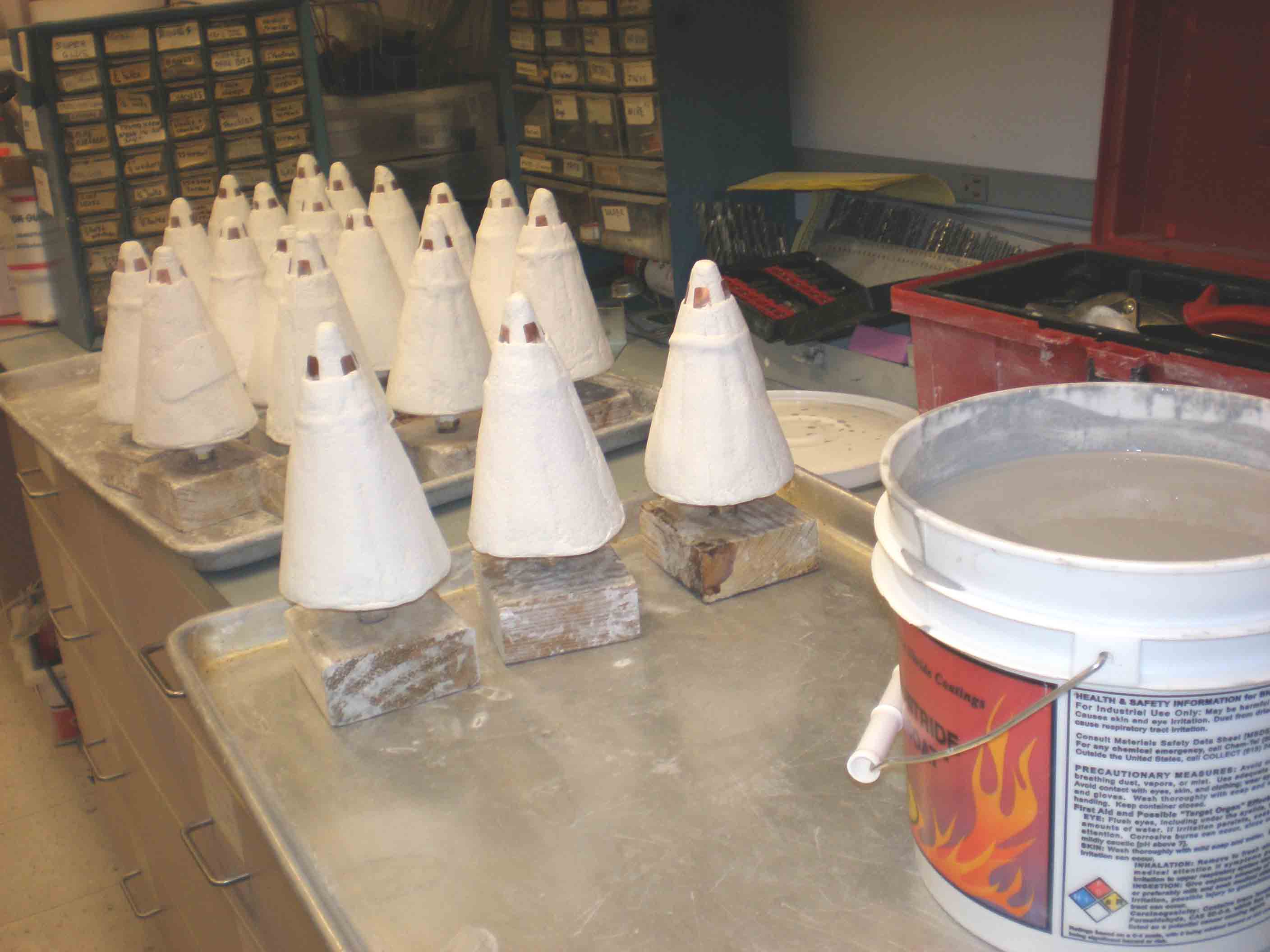
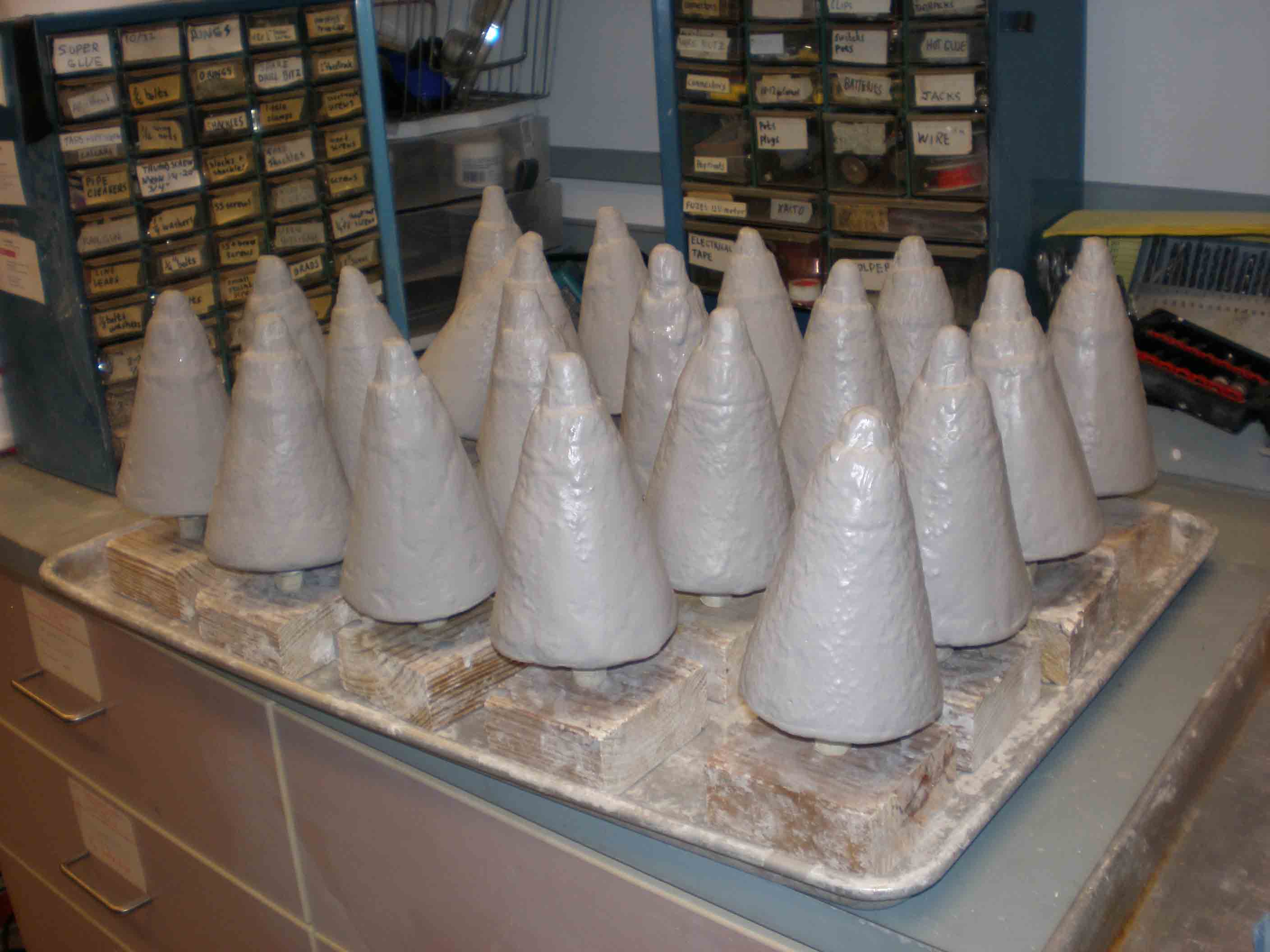
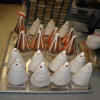
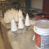
Dipped antennas
Using hard-coat BN paint, I dipped the antennas; this was probably too thick and I should have brushed it on, but it adhered well on about half the antennas
|
|
|
|
 |
|
Dipped antennas
|
|
 |
|
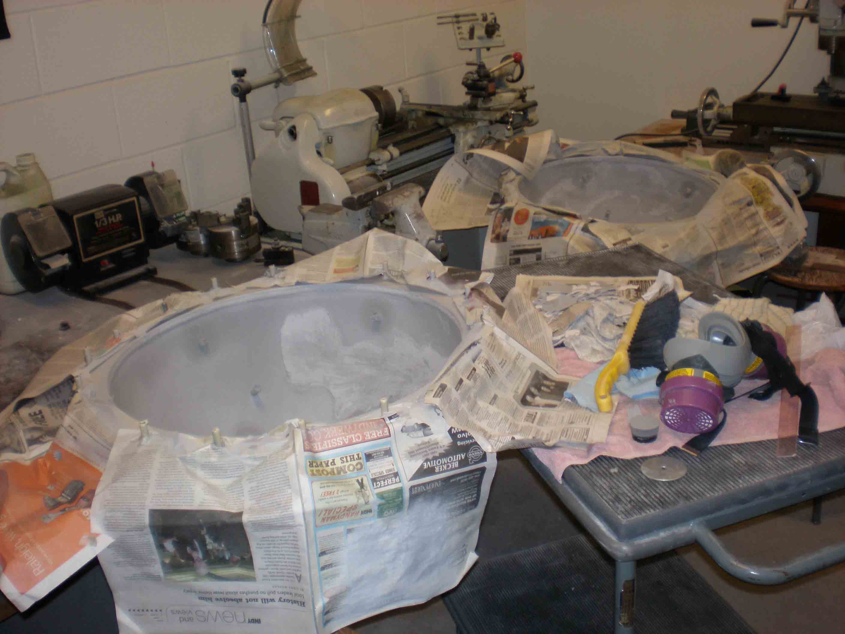
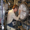
Framework minus the hemispheres
Took the hemispheres off the frames to bring them to the shop down the hall to spray BN paint on the inner surfaces
|
|
 |
|
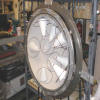
First spray
Initially I sprayed the BN paint over the existing clay-based ceramic, which also was powdery and had to be stabilized
|
|
 |
|
First spray with BN
BUT turns out the clay ceramic is too weak and peeled in several places; after this dried I took all the ceramic off and resprayed on bare metal (pics in the next gallery)
|
|
|