Lab Pictures 2
October and November 2006;
Room 102-A, Research II
NCSU, Raleigh NC
For economic reasons, and also since several
fittings are custom and not commercially available, I have made coax
connectors
and adapters by hand for each of the 20 antennas and magnetrons. There
are
inevitable reflections and losses, not to mention leaks, in the circuit
that
would require several thousand dollars of equipment to avoid and
correct. The
reactor works reasonably well at the intended pulse duration, but it
cannot be
considered anywhere near to optimal in safety and efficiency, and
cannot be run
CW. Each magnetron produces 1000 W; this is within the power rating of
the coax
cable, but only standard connectors would be durable and reliable even
with
pulsed operation (at the usual 0.2 s).
The first connector required for the 20
magnetrons lead from the antenna stub usually used to feed microwaves
into the
oven waveguide, into the coax cable instead. This required an inner and
an
outer cone, proportioned for 75 Ohm impedance. The cable connected by
sliding
the inner connector into the inner cone and squeezing the outer shield
onto the
outer cone with a hose clamp and conical aluminum pieces. This
technique worked
very well and proved durable and with no evidence of leakage or damage
over
three years of operation.
For
the first several months of construction, I anticipated winding magnets
and
fitting them around the pressure chamber as in the original proposal.
However
it became obvious, after I had constructed spindles for the magnets,
that this
would be expensive, elaborate, and probably impossible for me to
accomplish alone
in the time required and with only meagre student loans for financing.
After
operating the reactor it became clear that my original proposal was
entirely
too tidy and optimistic, and that the idealistic simplifications would
not
apply in the real world. The reactor design and hardware configurations
continued to evolve dramatically all the way to the fall of 2009, when
active
experimentation halted in order to write my thesis.
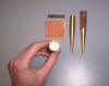
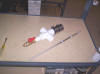
For
initial plasma formation and introduction of experimental aerosols
(vaporized
organic powders), I used a miniature coaxial plasma jet (the sparker)
at the end of ¼ inch
outer diameter stainless tubing about 65 cm long. The inner electrode
was a 5
inch long, 1/16 inch diameter tungsten welding rod, with the cavity at
the last
half inch, the rest sealed with a low-temperature glass frit backed up
with
porcelain. The current pulse (negative from the capacitors) went along
the
central tungsten electrode, through the target material placed in the
end
(organic powder with carbon dust), and back through the stainless tube
to
ground outside the sphere. It ran in the south polar pipe and just past
the
inner baffles, carefully insulated from all metal contact, since any
path to ground
besides the intended one eroded a good deal of metal by intense
sparking.
|
 |
|
Cones taper from magnetron antenna stubs to coaxial
cores (75 ohm)
|
|
 |
|
Cones mounted on magnetron antenna stubs
|
|
 |
|
Rubber plugs seal 1/2 holes, 10 ga. copper wire for
antenna
|
|
 |
|
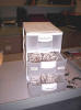
Collection of 20 antennas
|
|
 |
|
Copper helical antenna coated with ceramic
|
|
|
 |
|
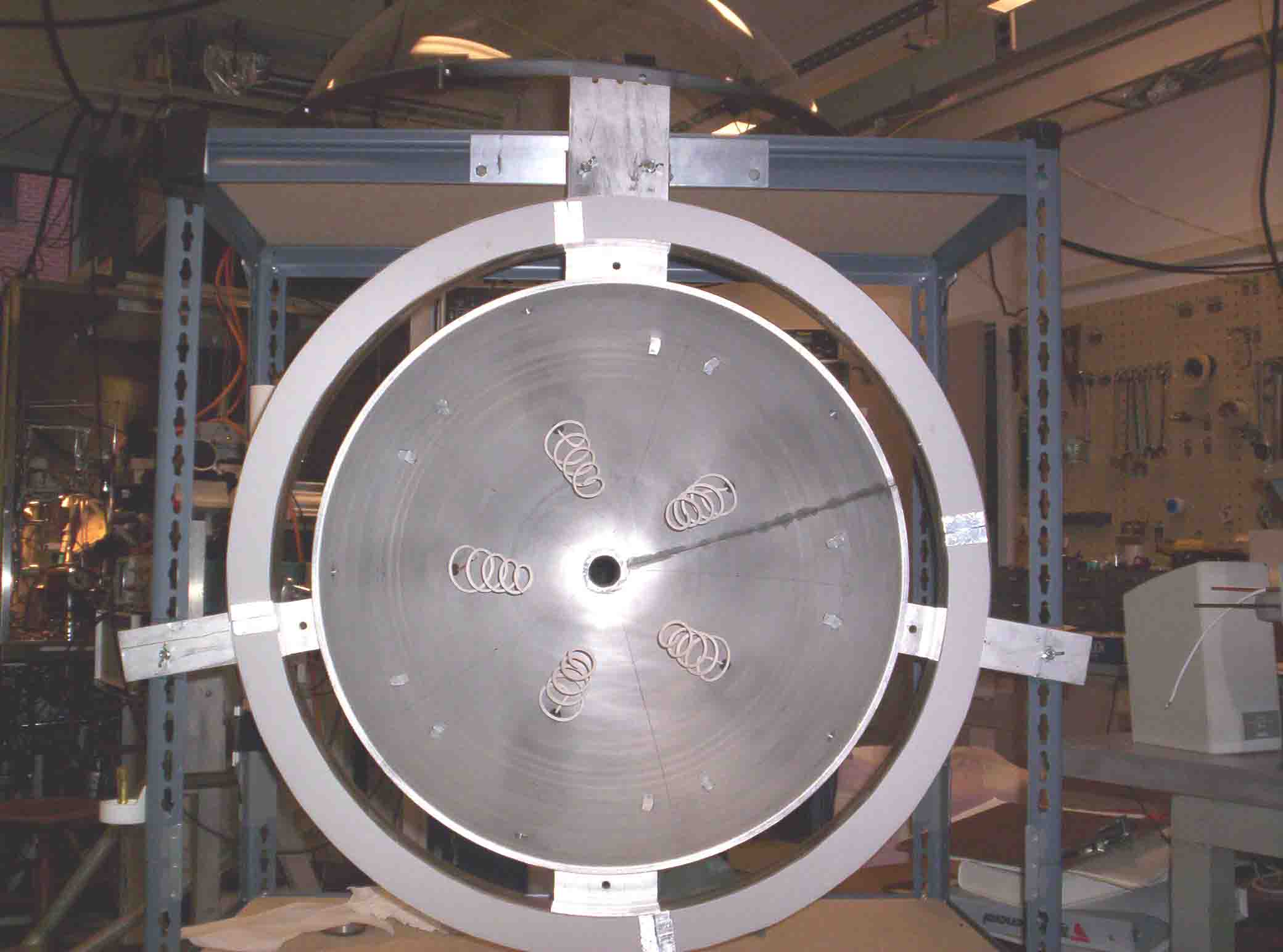
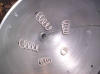
5 polar antennas without baffles
|
|
 |
|
5 polar antennas, no baffles
|
|
 |
|
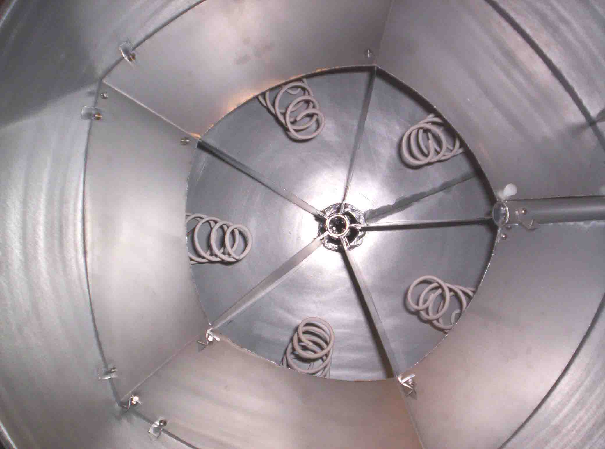
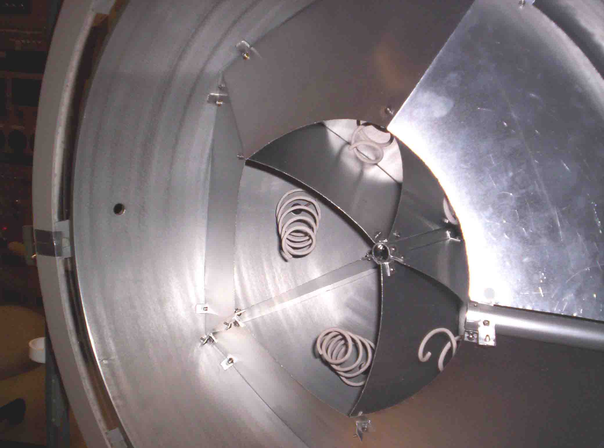
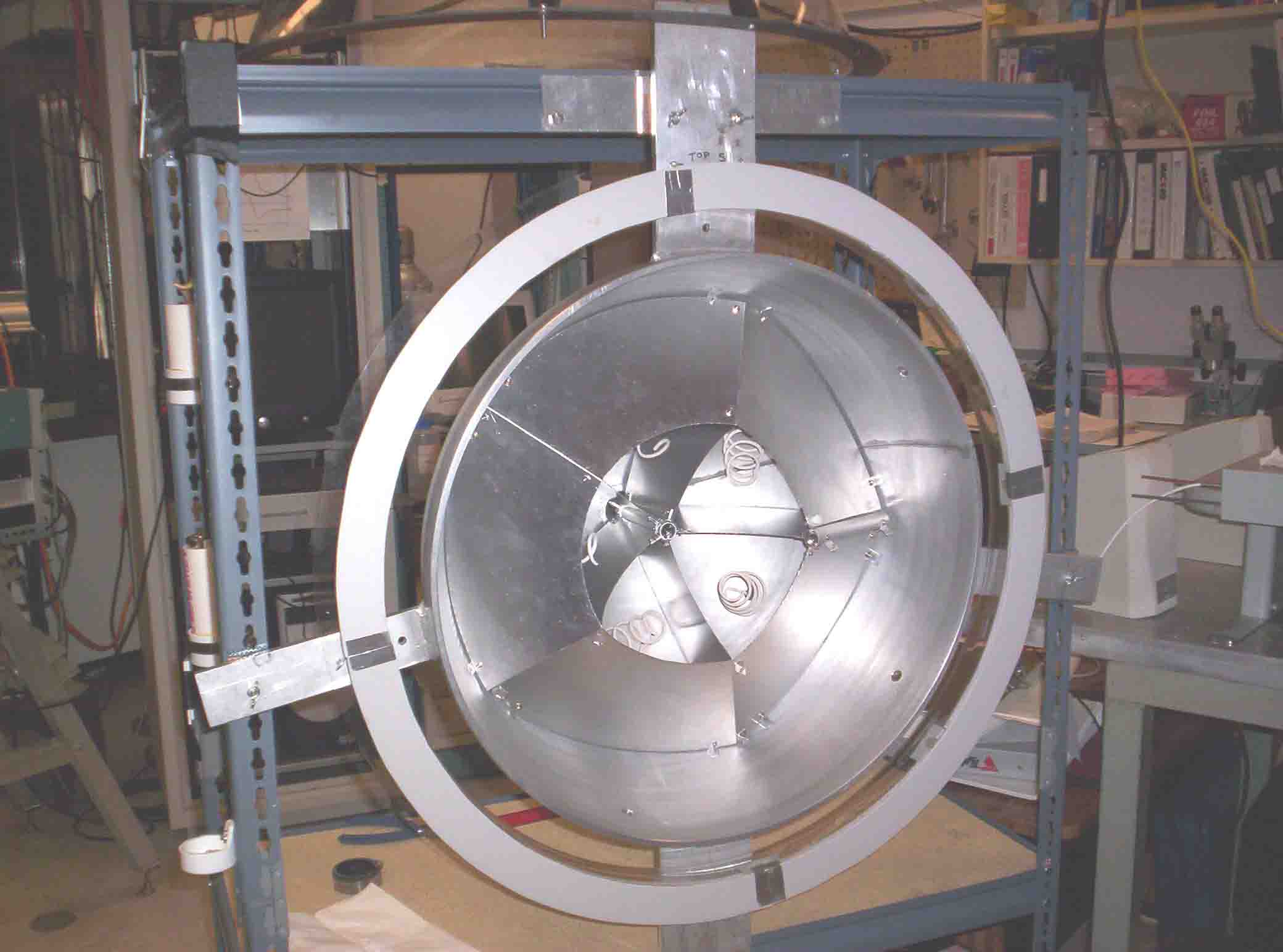
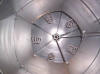
5 polar antennas with their baffles
|
|
 |
|
5 polar antennas
|
|
 |
|
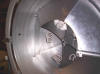
Can't resist such a cool shot
|
|
|
 |
|
First coax attached
|
|
 |
|
Coax through home-made connectors to antennas
|
|
 |
|
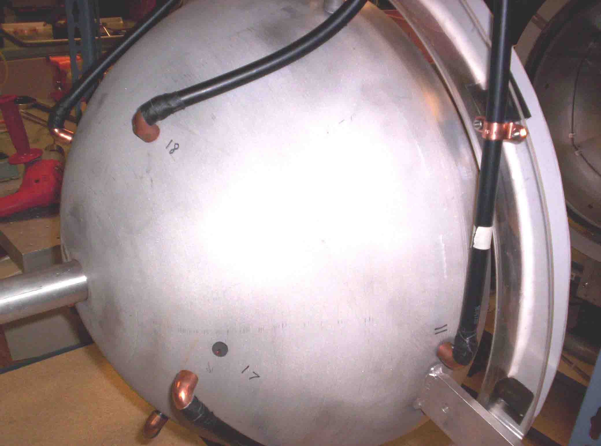
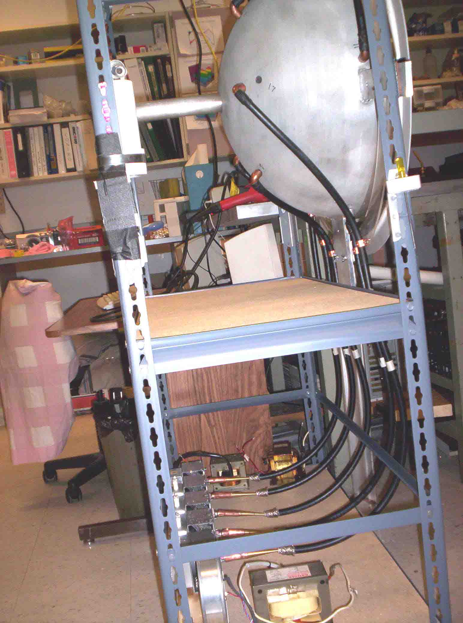
Coax from lower 5 magnetrons to antennas, South
hemisphere
|
|
 |
|
Coax attached, midsection South hemisphere
|
|
 |
|
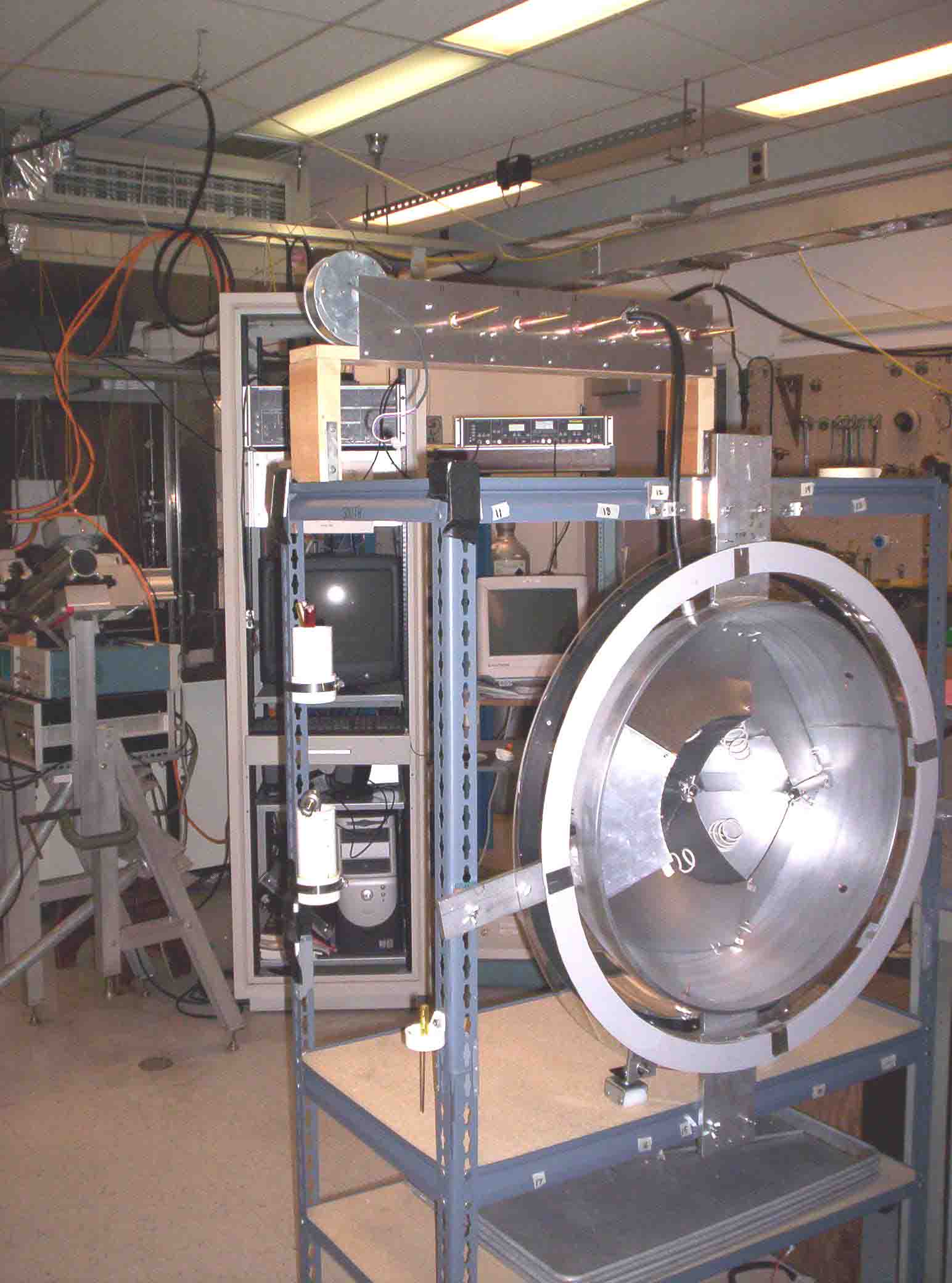
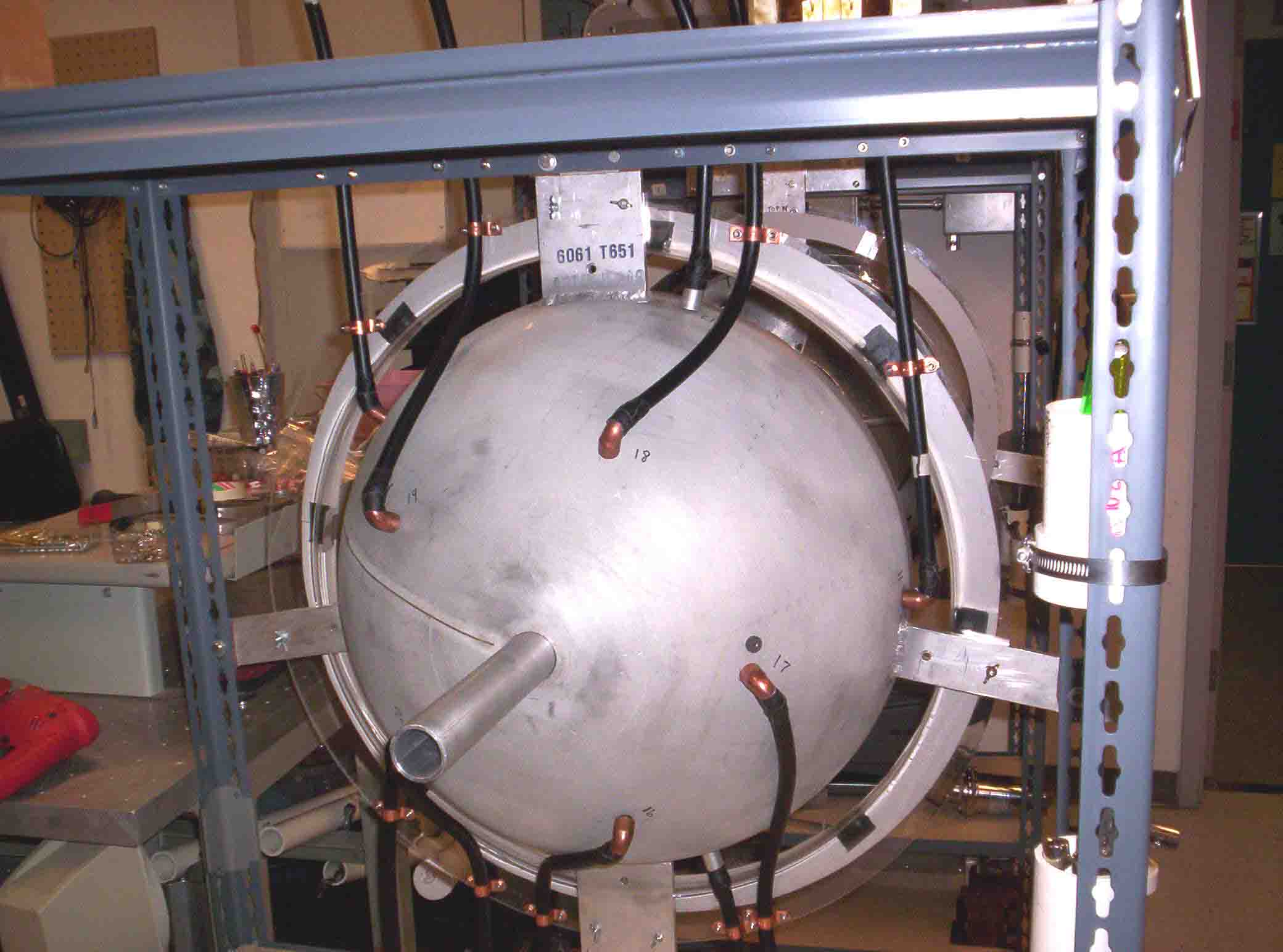
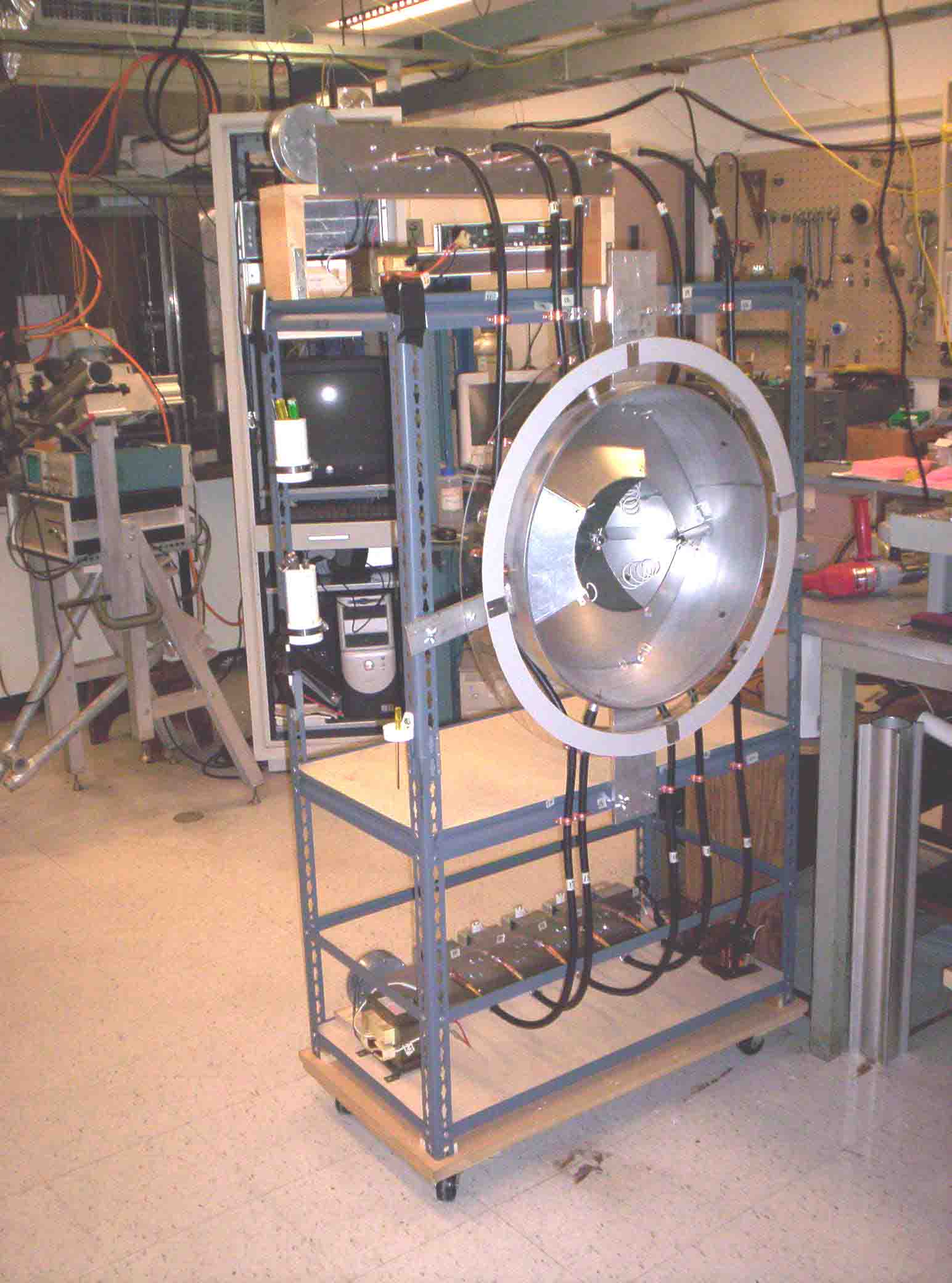
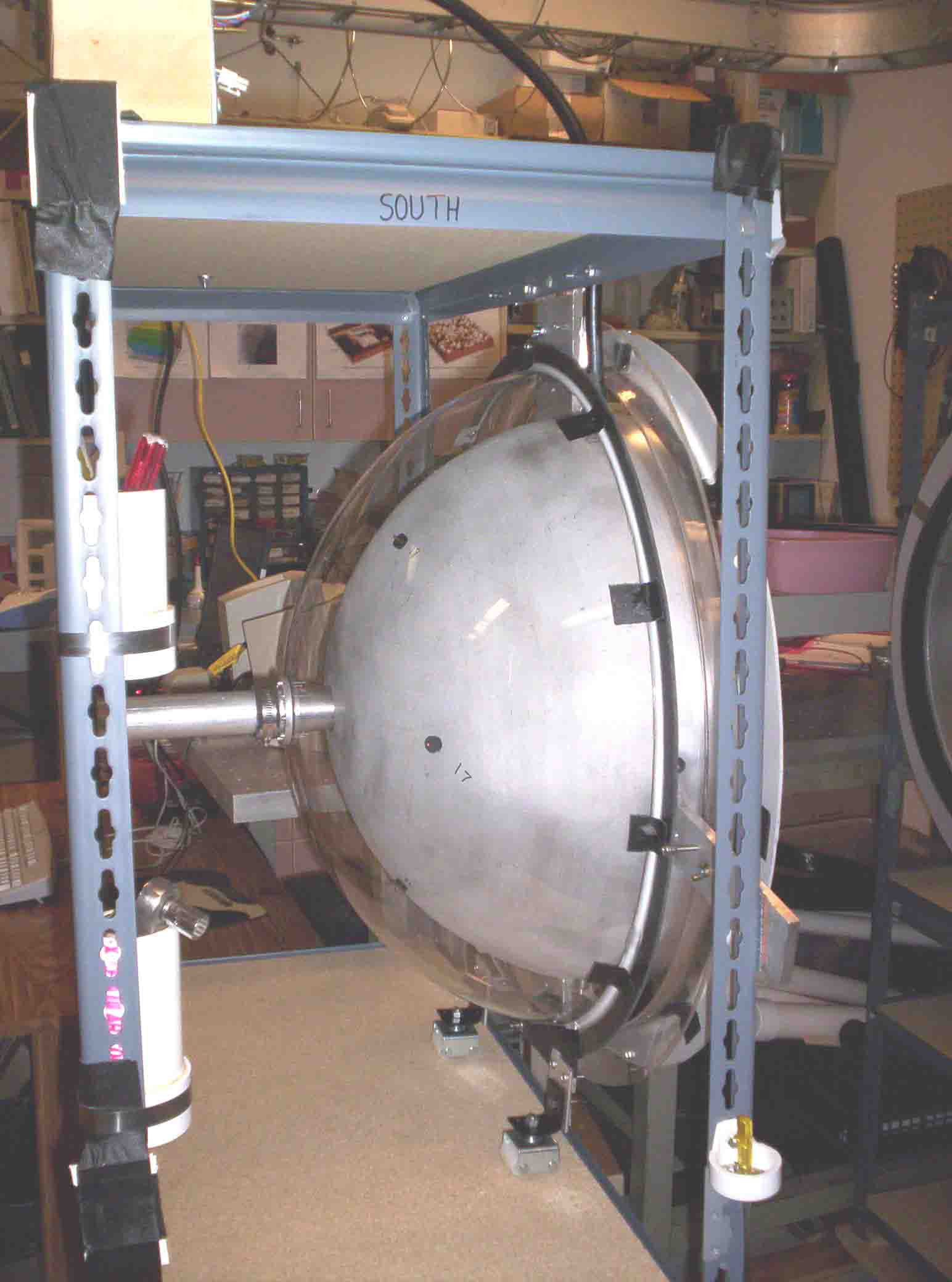
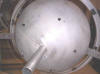
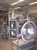
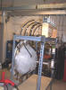
Overview South hemisphere with coax
|
|
|
 |
|
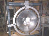
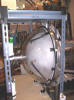
Coax with plastic magnet spindle in place
|
|
 |
|
Upper 5 coax cables South hemisphere
|
|
 |
|
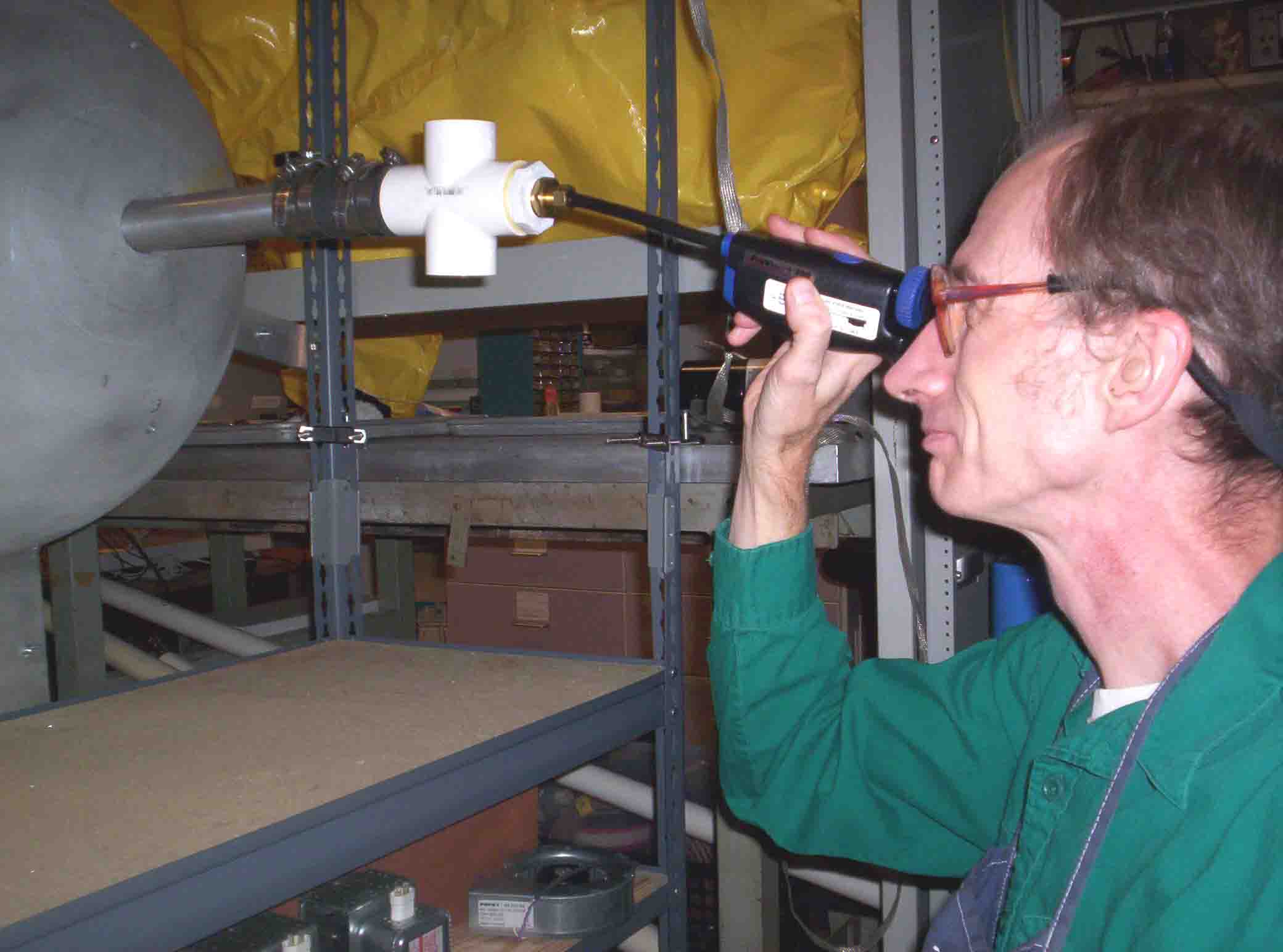
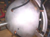
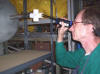
Borescope (ProVision 300) enters N pole
|
|
 |
|
Hey! I see something!
|
|
 |
|
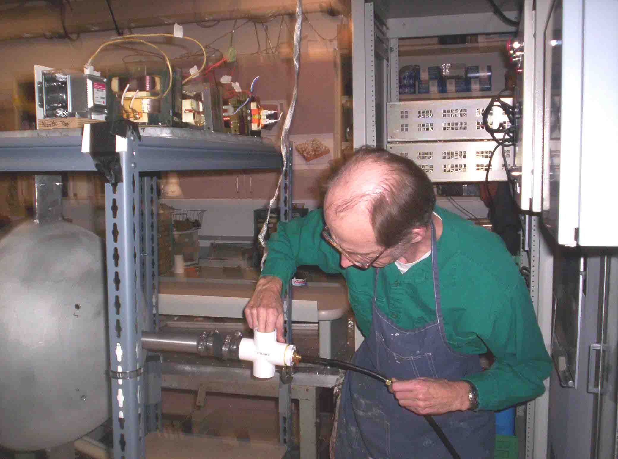
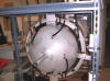
Fitting borescope through polar pipe
|
|
|
 |
|
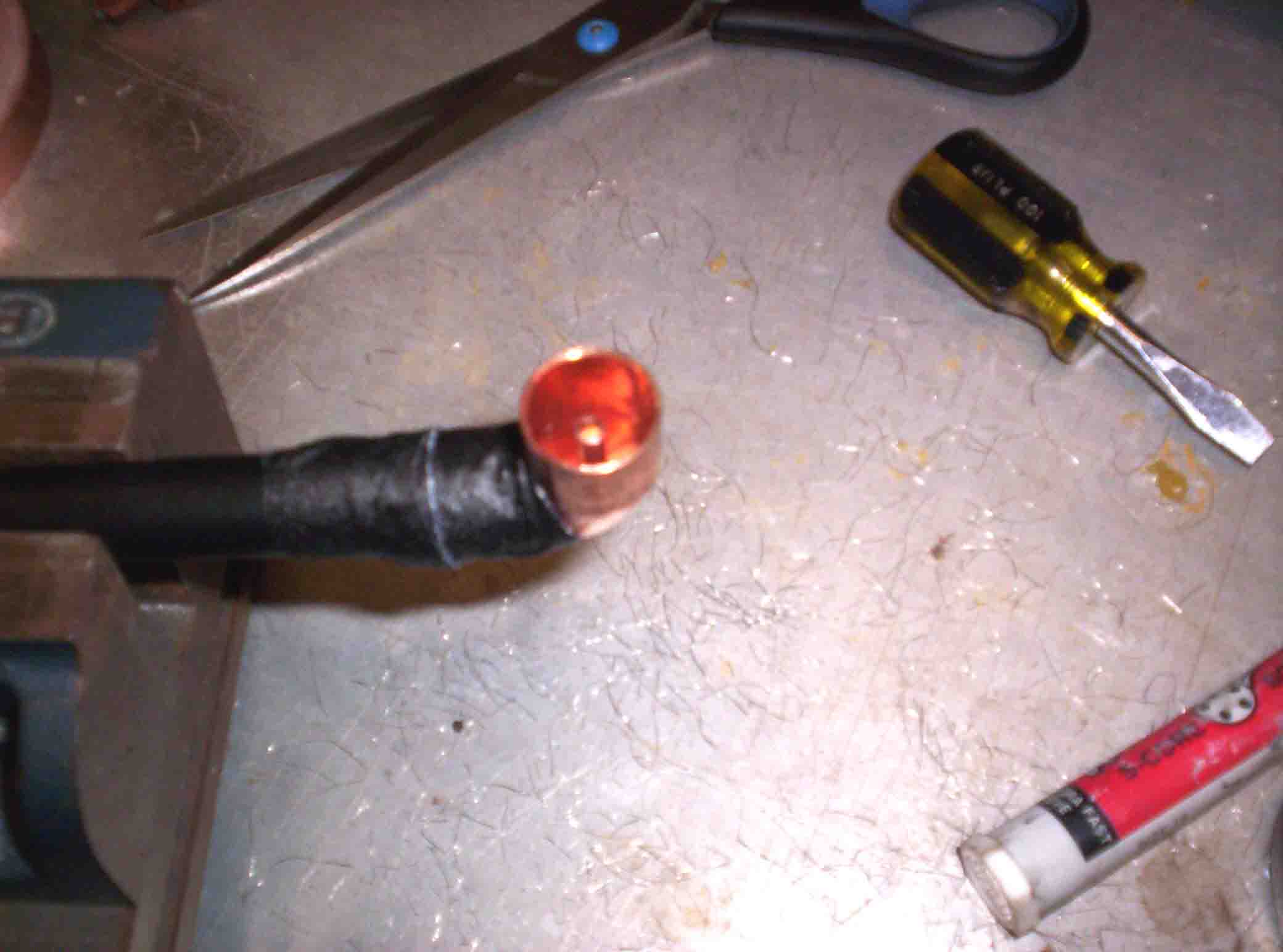
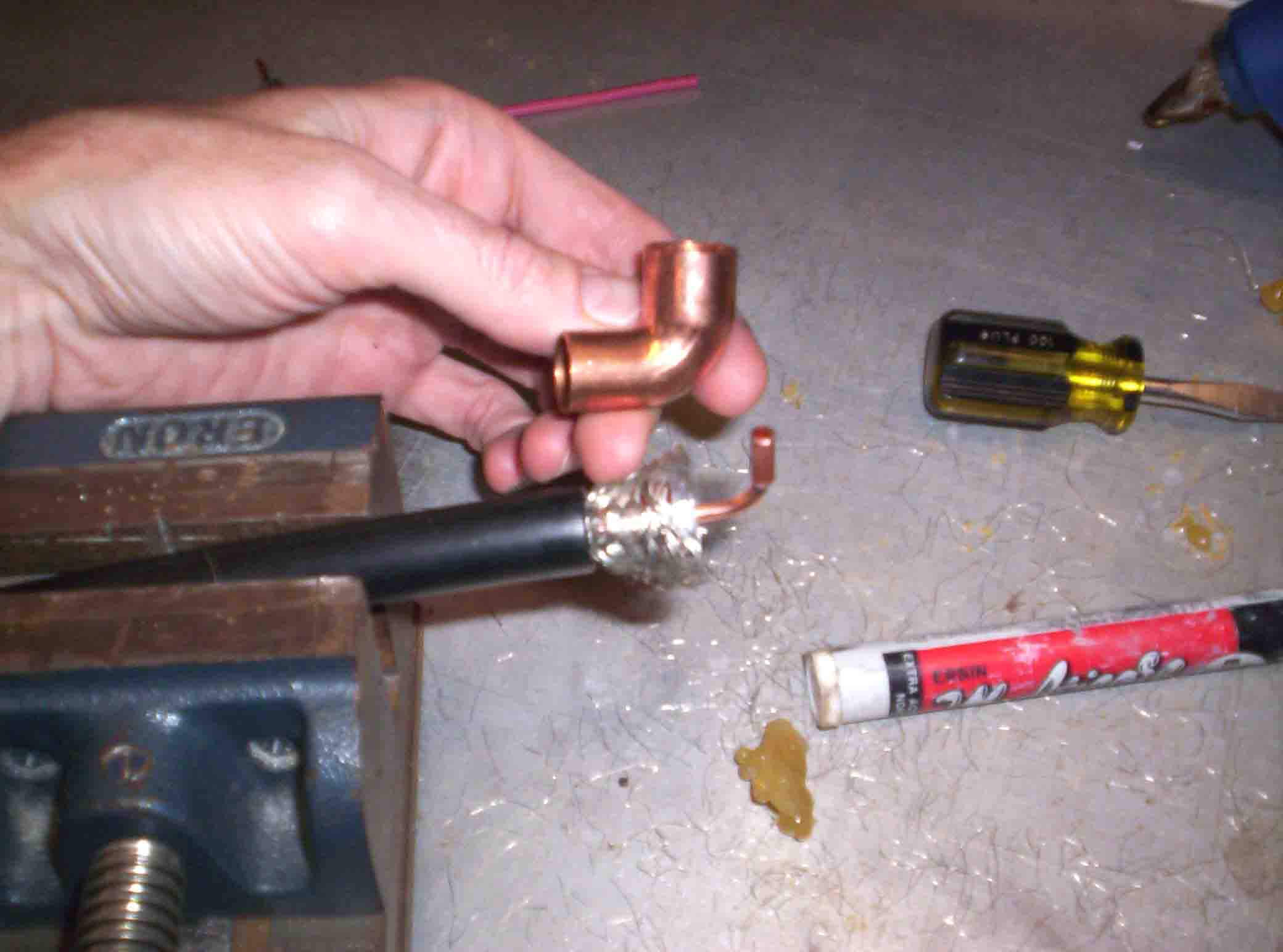
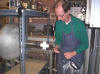
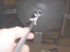
Making right-angle coax connector from plumbing parts
|
|
 |
|
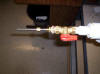
Soldering small tube onto coax core, covering with
copper plumbing part
|
|
 |
|
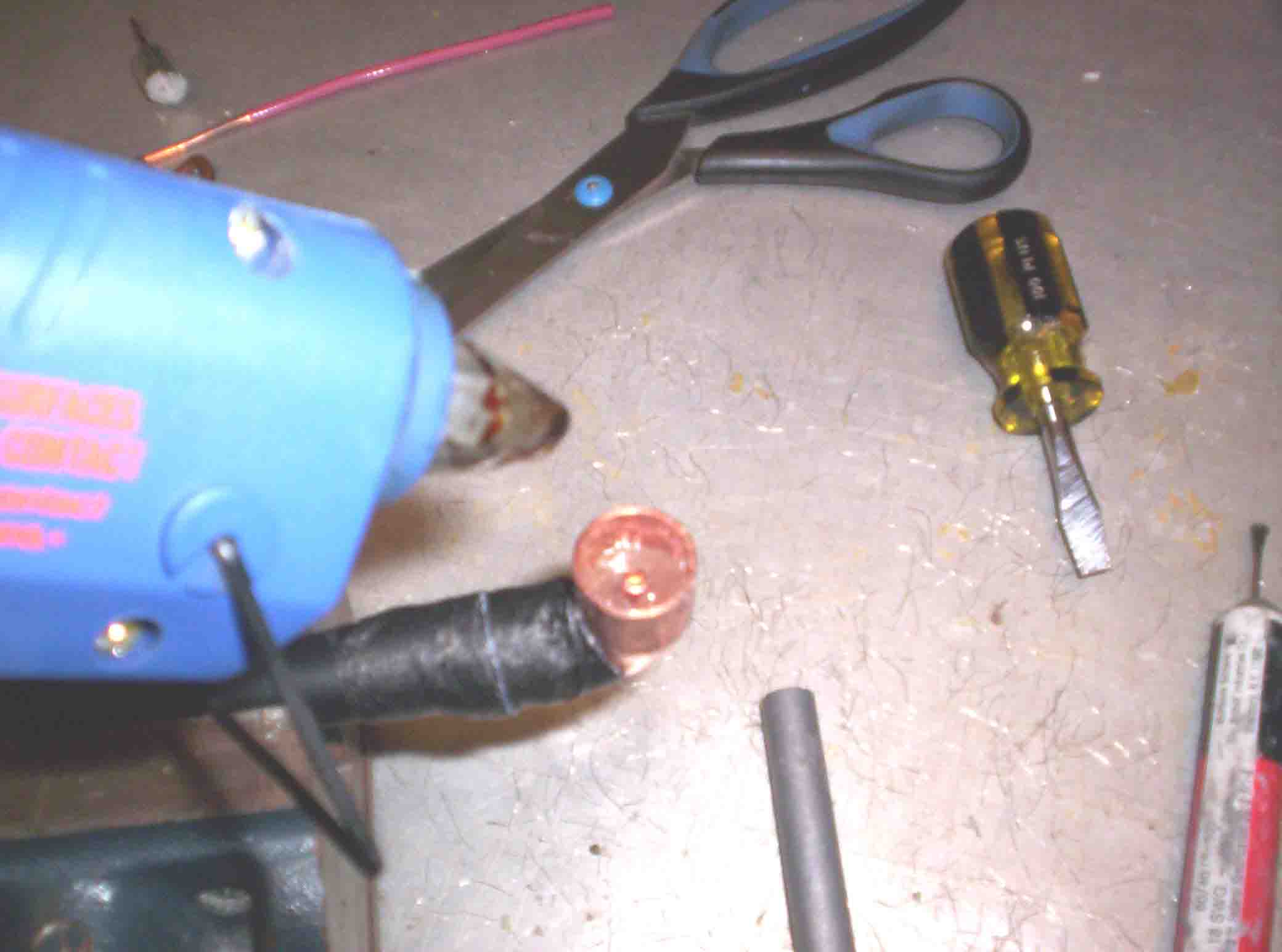
Filling connector with hot glue
|
|
 |
|
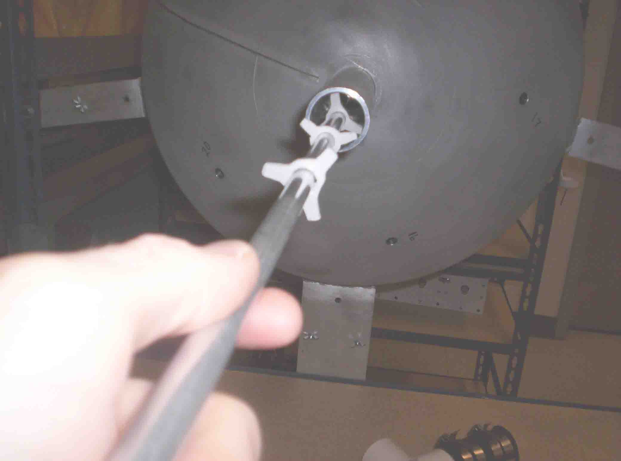
Coaxial sparker goes through this guide tube along polar
axis through baffles
|
|
 |
|
Centering guide with PVC spacers
|
|
|
 |
|
Valve, hose clamps, center guide for sparker (S
hemisphere)
|
|
 |
|
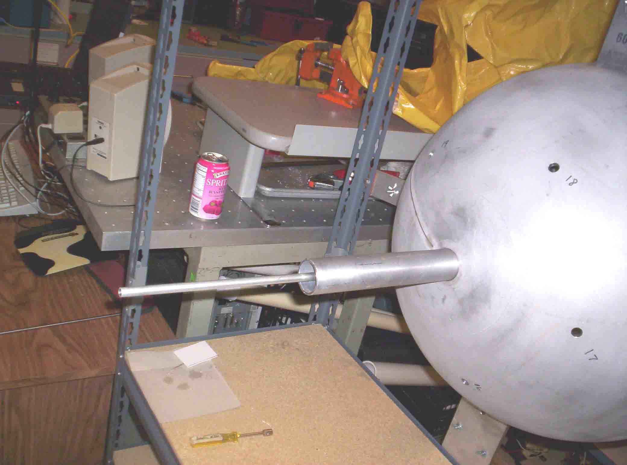
Valve with coax sparker tube (stainless steel, 1/4
inch); allows removal while keeping vacuum or gas mixture
|
|
 |
|
Sparker valve
|
|
 |
|
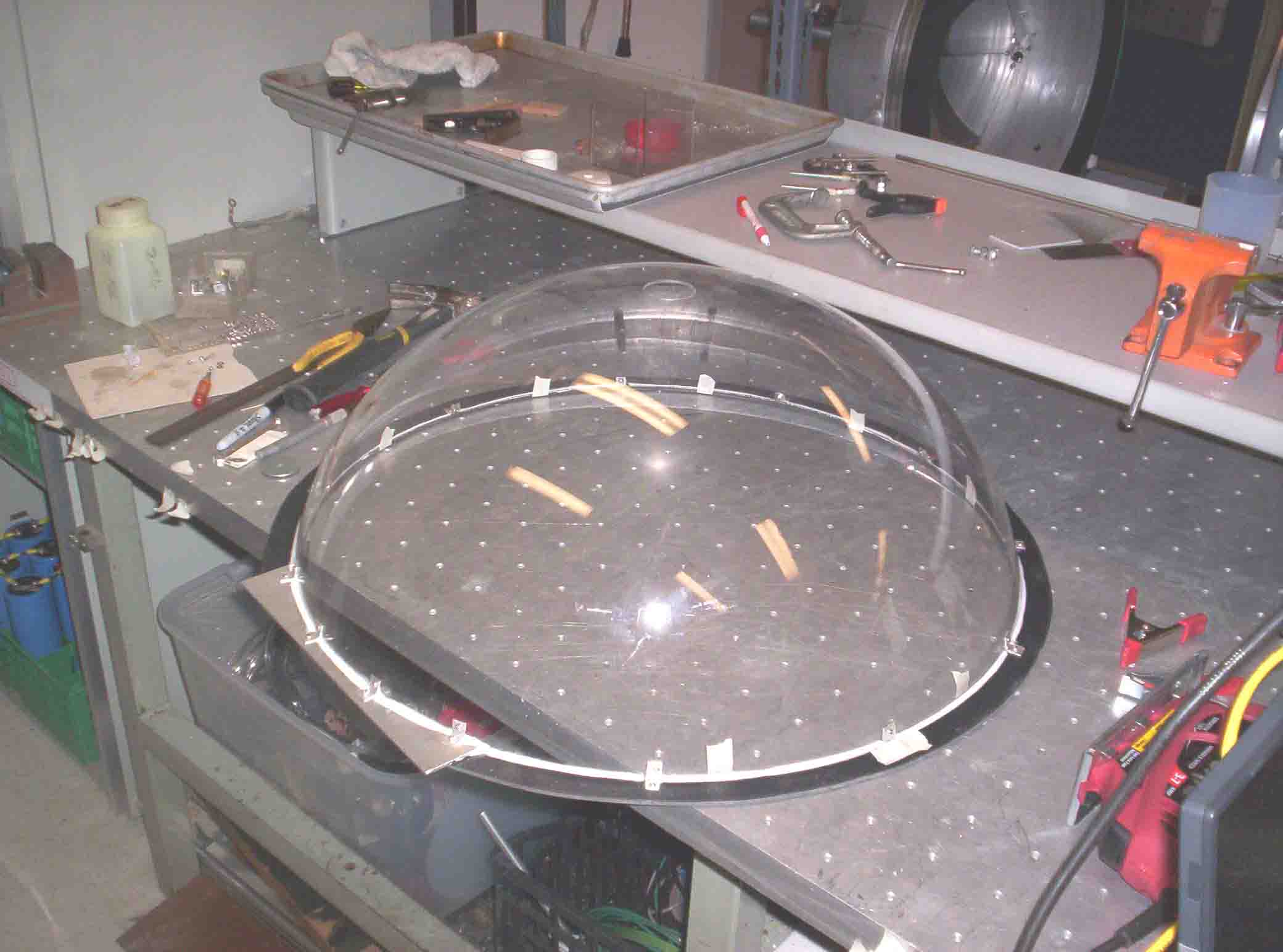
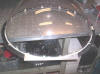
Magnet spindle construction; PVC hemisphere sliced and I
added this flange
|
|
 |
|
Magnet spindle construction
|
|
|
 |
|
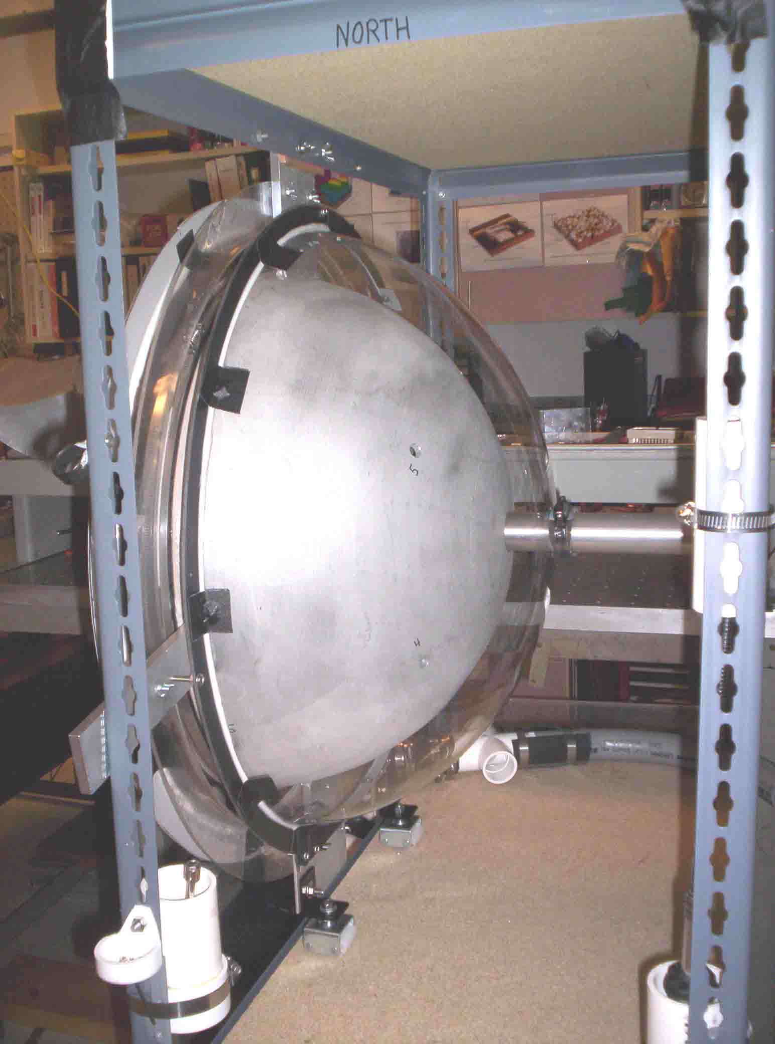
Mounting spindle
|
|
 |
|
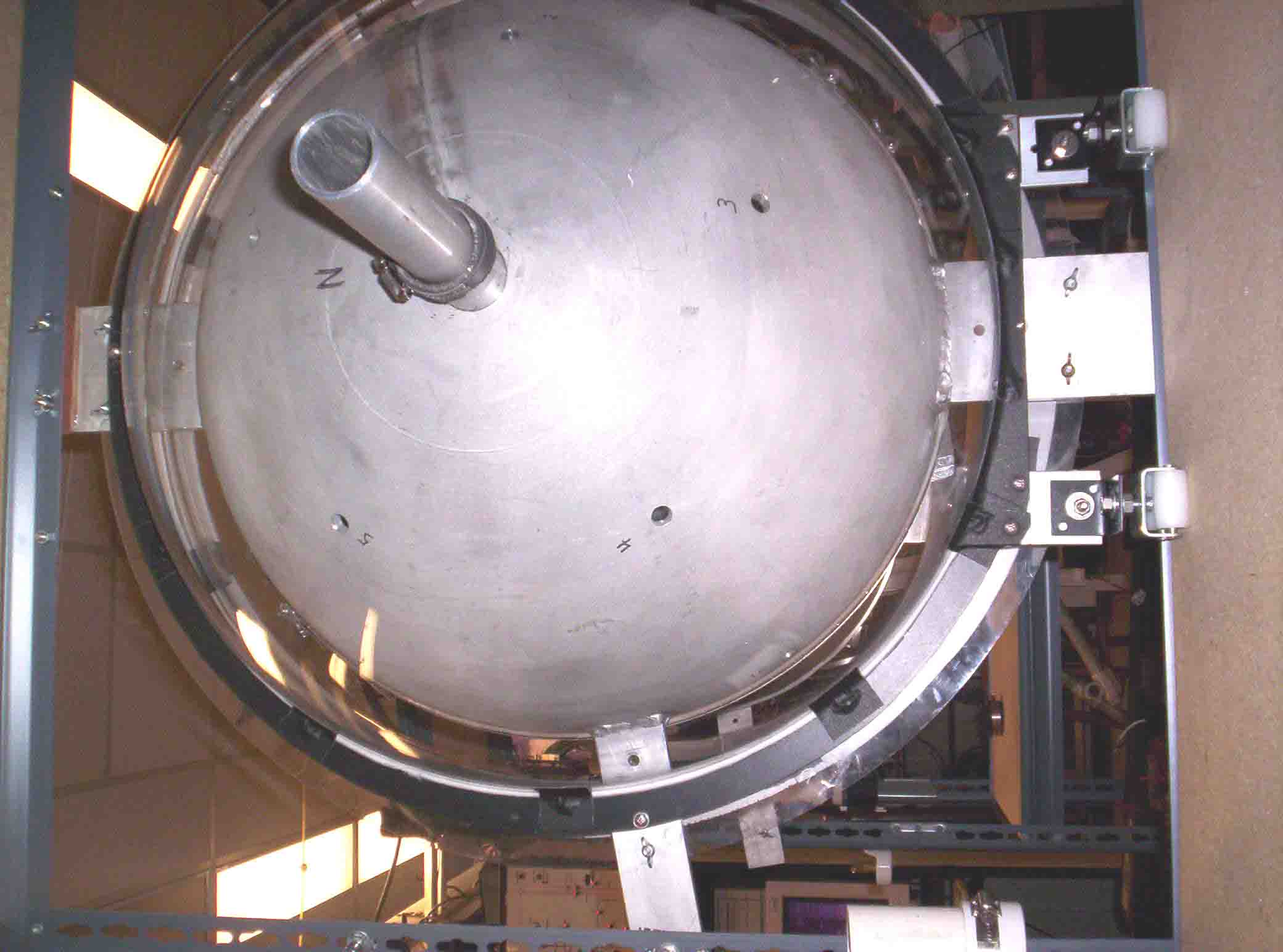
Mounted spindle
|
|
 |
|
Mounted spindle; won't need the magnet for ball
lightining experiments
|
|
 |
|
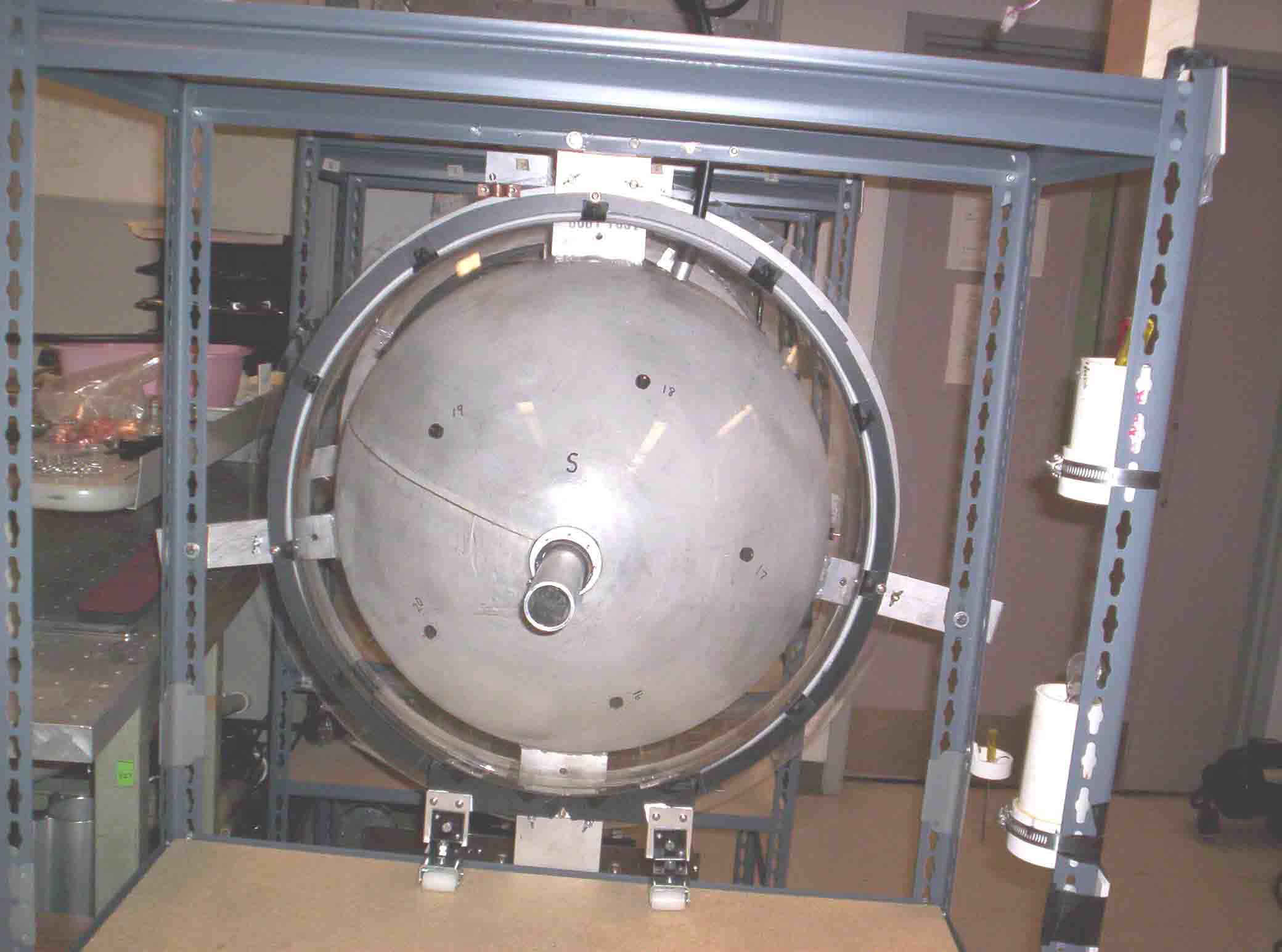
This spherical magnet provides the cylindrical cusp
field required for SMC
|
|
|