|
|
 |
|
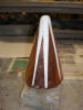
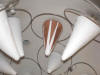
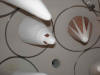
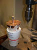
Early cone shield
trial pattern, without external ceramic
|
|
 |
|
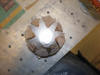
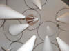
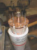
Early shield
end view
|
|
 |
|
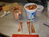
Removing bad magnetron
Blew one up...
|
|
 |
|
Bad mag
Everything is made to be replaced--I toast things
|
|
 |
|
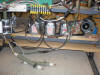
Trial of early shield
Other antennas unshielded, all the power goes out from the base as a result; note grid rings
|
|
|
|
 |
|
Early shield mounted
|
|
 |
|
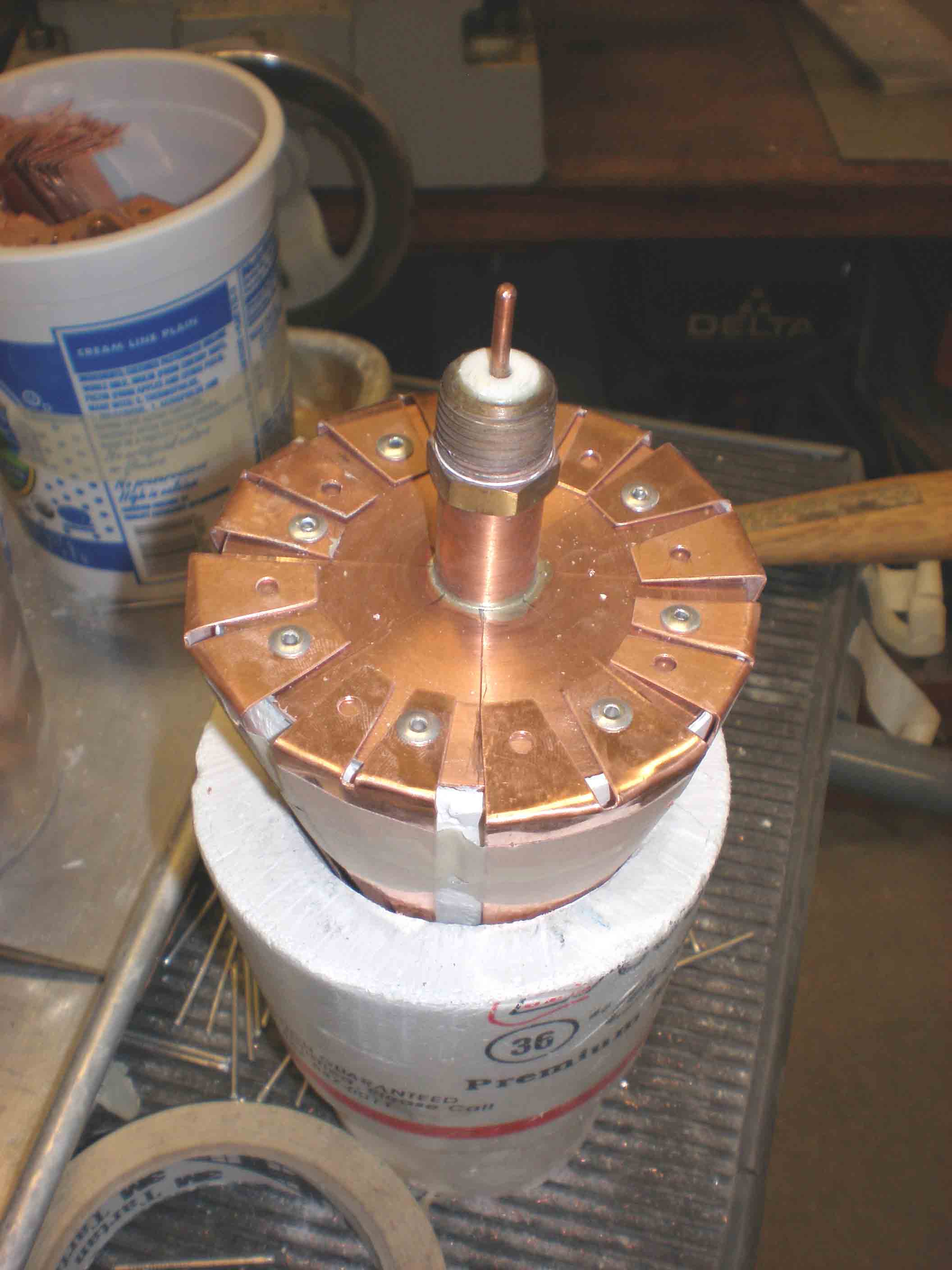
Constructing base of shield
Used rivets to attach triangles to 1/16" copper disk
|
|
 |
|
Me with trial antenna
|
|
 |
|
Shield hoop
Wire required to hold triangles tight against ceramic and to connect ground at microwave frequencies, soldered to each triangle (it won't be getting hot)
|
|
 |
|
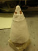
Coated with ceramic
Using silica composite ceramic sheet that does not require heat curing
|
|
|
|
 |
|
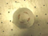
End view Mark II antenna
Inner tips of shield are bare to allow current from the grid to the tips
|
|
 |
|
Mark II mounted for test
|
|
|
|
 |
|
Close up mounted Mark II
First completed antenna ready to test: turns out this ceramic kicks up a lot of dust when in contact with plasma
|
|
|
|
 |
|
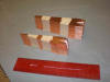
Triangle stack
Getting ready to make the other 19 antennas
|
|
 |
|
Shaping triangles to fit
Putting a bit of conical curve to the triangles
|
|
 |
|
Shaping triangles
Took a long time!
|
|
 |
|
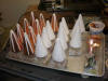
Mounting shields
The white cones are the epoxy cores with the conical helix of copper wire inside, coated with the silica ceramic composite
|
|
 |
|
Drilling for rivet holes
Used aluminum pop rivets; worried a bit about trapped gas; ideally the whole thing would be monolithic, cast, and fired with low-expansion metal
|
|
|
|
 |
|
Riveting triangles to base
|
|
 |
|
Riveting
|
|
 |
|
Riveted
|
|
|
 Lab Pictures 8