|
|
 |
|
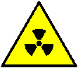
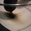
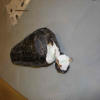
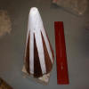
Mark 1 base damage
What happens when plasma hit the Mark 1 base...not pretty
|
|
 |
|
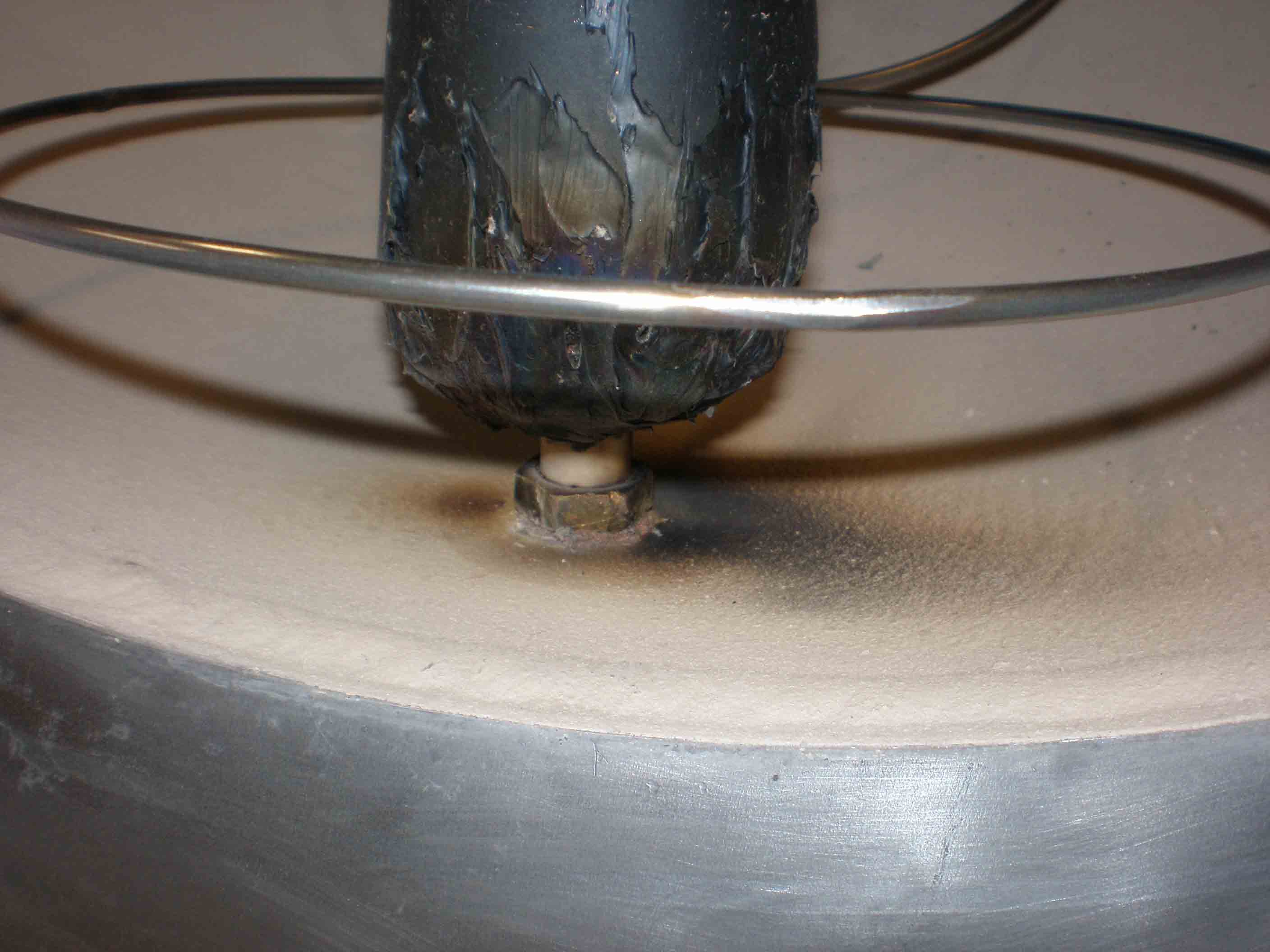
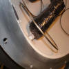
Mk 1 base
closeup of carnage (smelled bad too)
|
|
 |
|
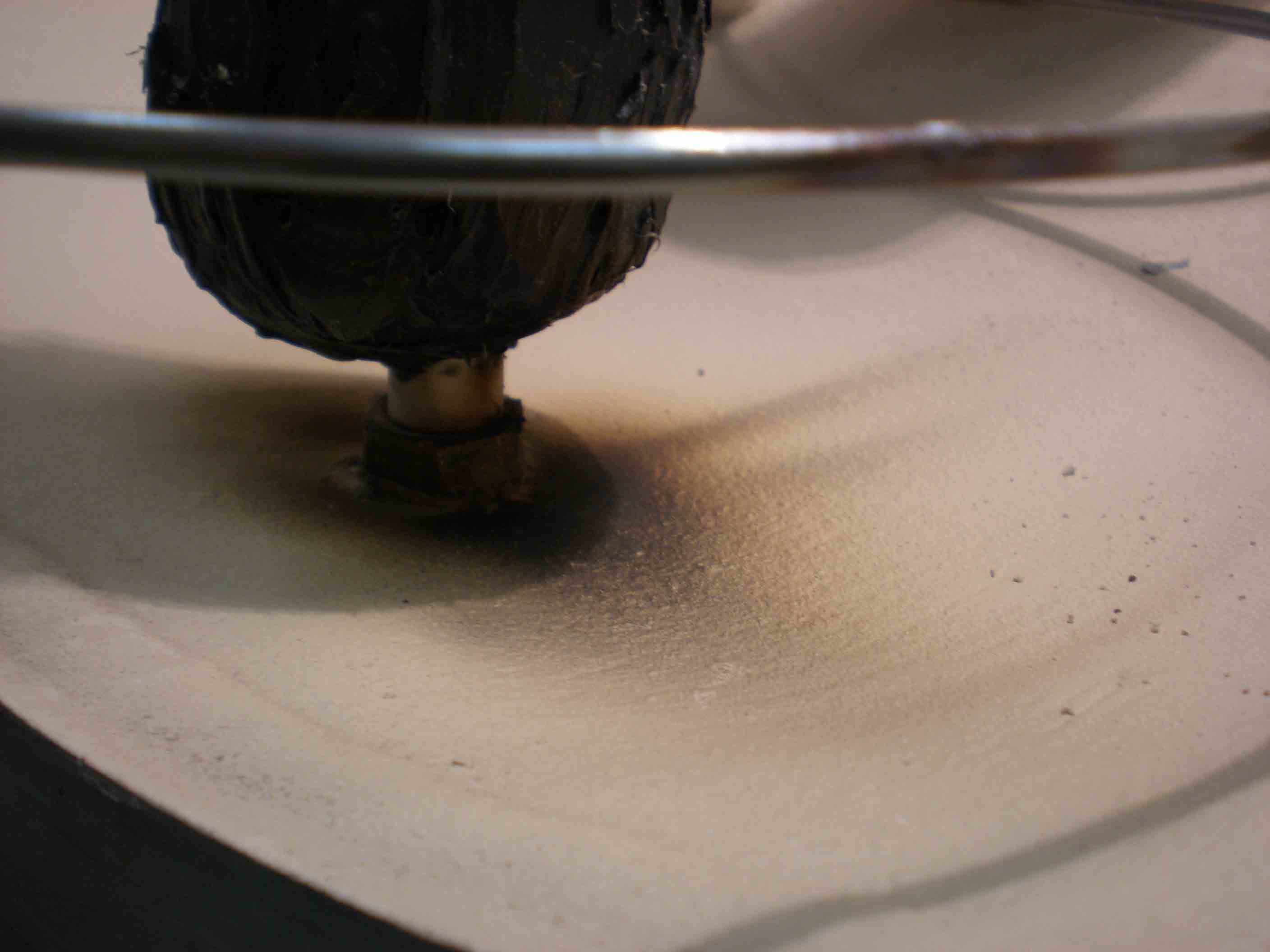
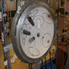
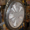
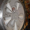
Mark 1 trial
with the grid added and foil shielding (which didn't work)
|
|
 |
|
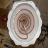
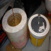
Mark 2 coil
in plaster of paris mold; this attempt to use boron nitride for mold release was a FAILURE
|
|
 |
|
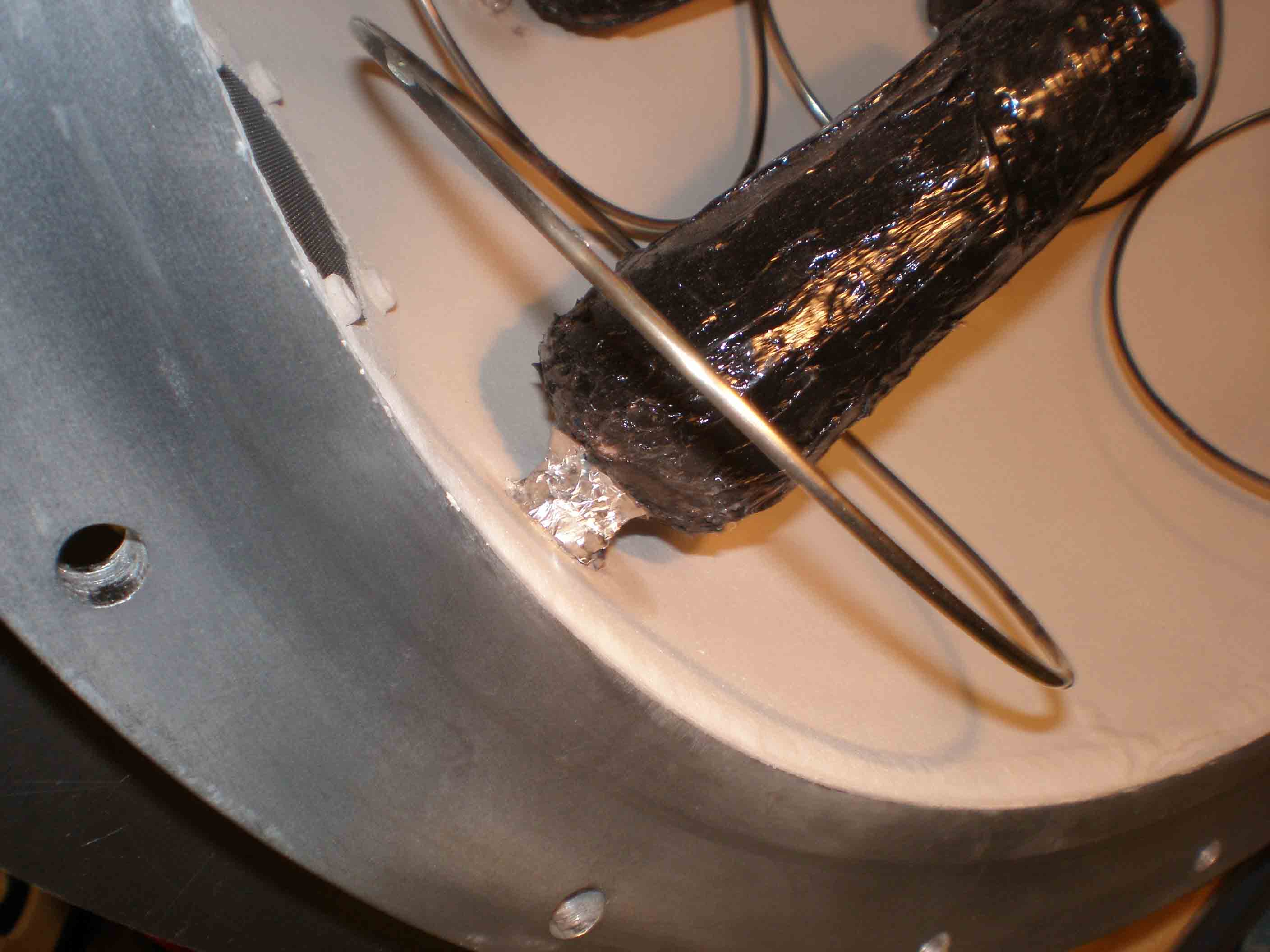
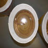
Mark 1 pattern trial
aluminum foil and aluminum tape shielding patterns; the middle one worked best
|
|
|
|
 |
|
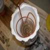
first pour epoxy
had to cure a bit at a time (four pours) to prevent overheating
|
|
 |
|
second pour epoxy
|
|
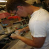 |
|
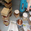
Chris sanding cones
|
|
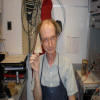 |
|
me with the first bare Mark2 cone
|
|
 |
|
Close-up of epoxy coil
|
|
|
|
 |
|
Mark 1 antenna
with triangular aluminum tape shield, ceramic composite about to be applied
|
|
 |
|
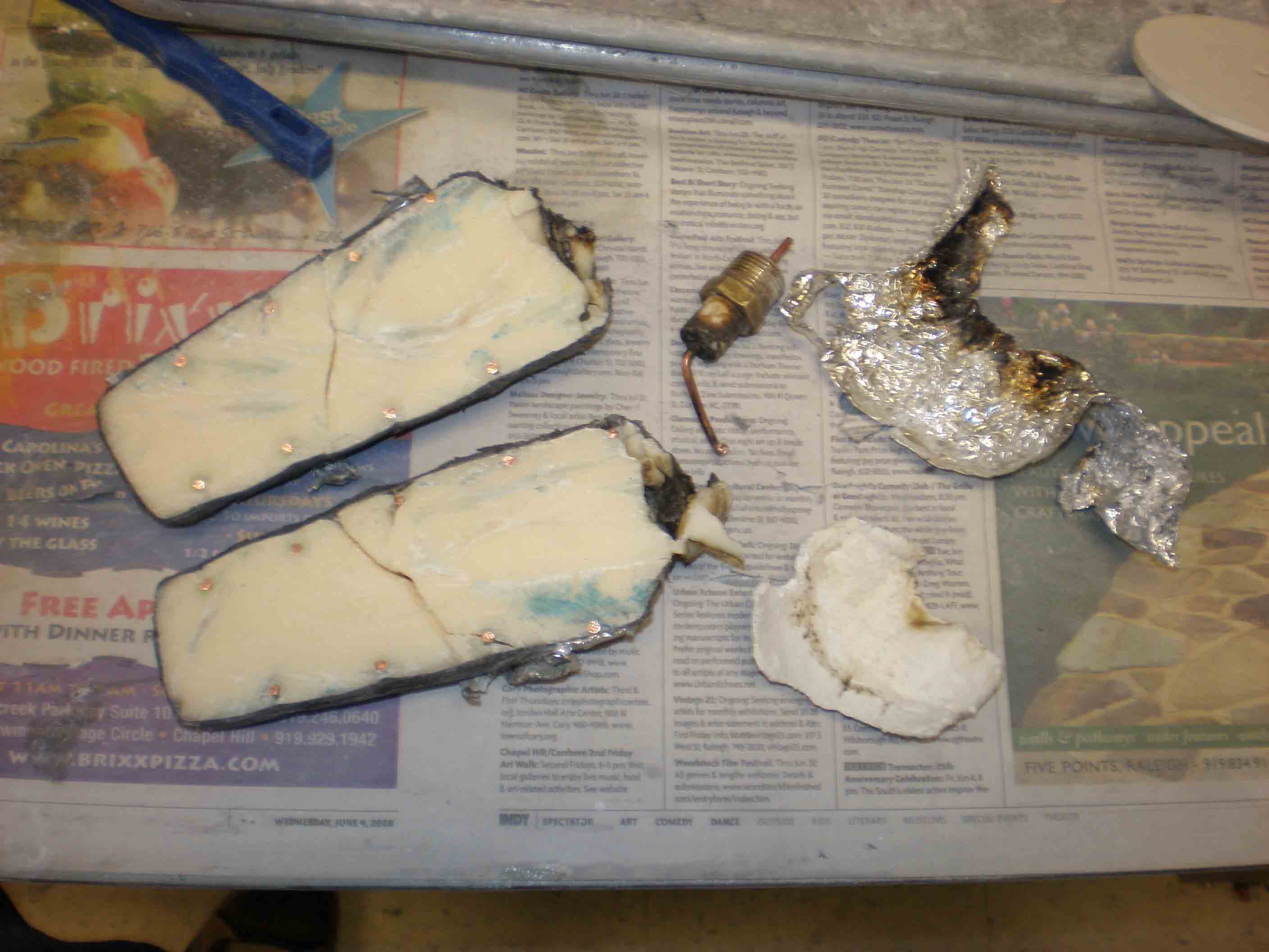
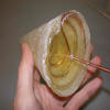
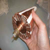
blown Mark 1 antenna
showing polyclay, copper wire
|
|
 |
|
casting Mark 2 cones
PVC plug on right, making plaster cast; completed pour on left
|
|
 |
|
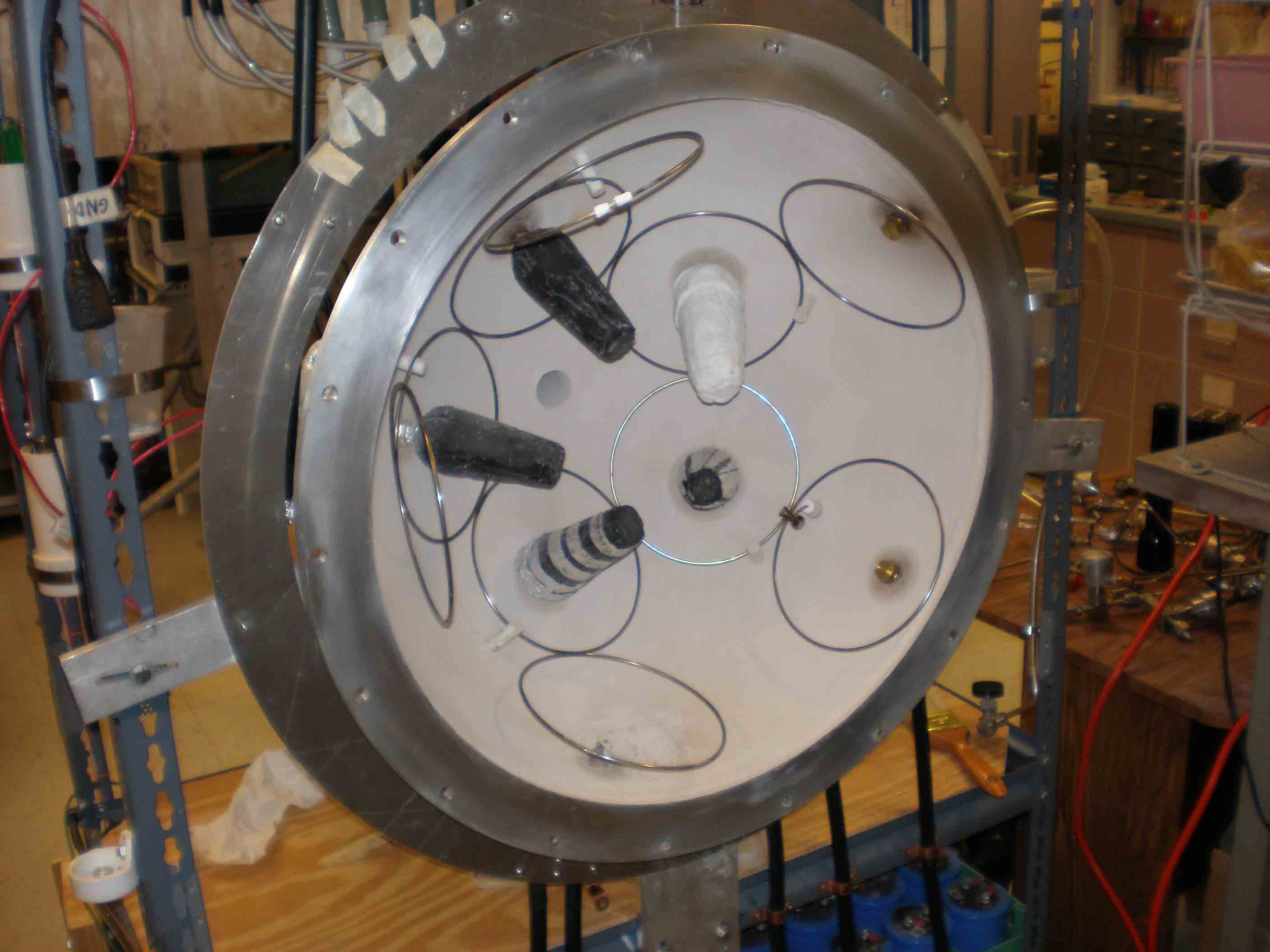
South hemisphere test
with three patterns including ceramic coating along with just black silicone
|
|
 |
|
casting Mark 2 antennas
I used vaseline for mold release
|
|
|
|
 |
|
looking down into mold
|
|
 |
|
new copper bases
machined ceramic fits into copper pipe; copper plate at base of the cone
|
|
 |
|
Chris with epoxy cones
|
|
 |
|
new epoxy cones
|
|
 |
|
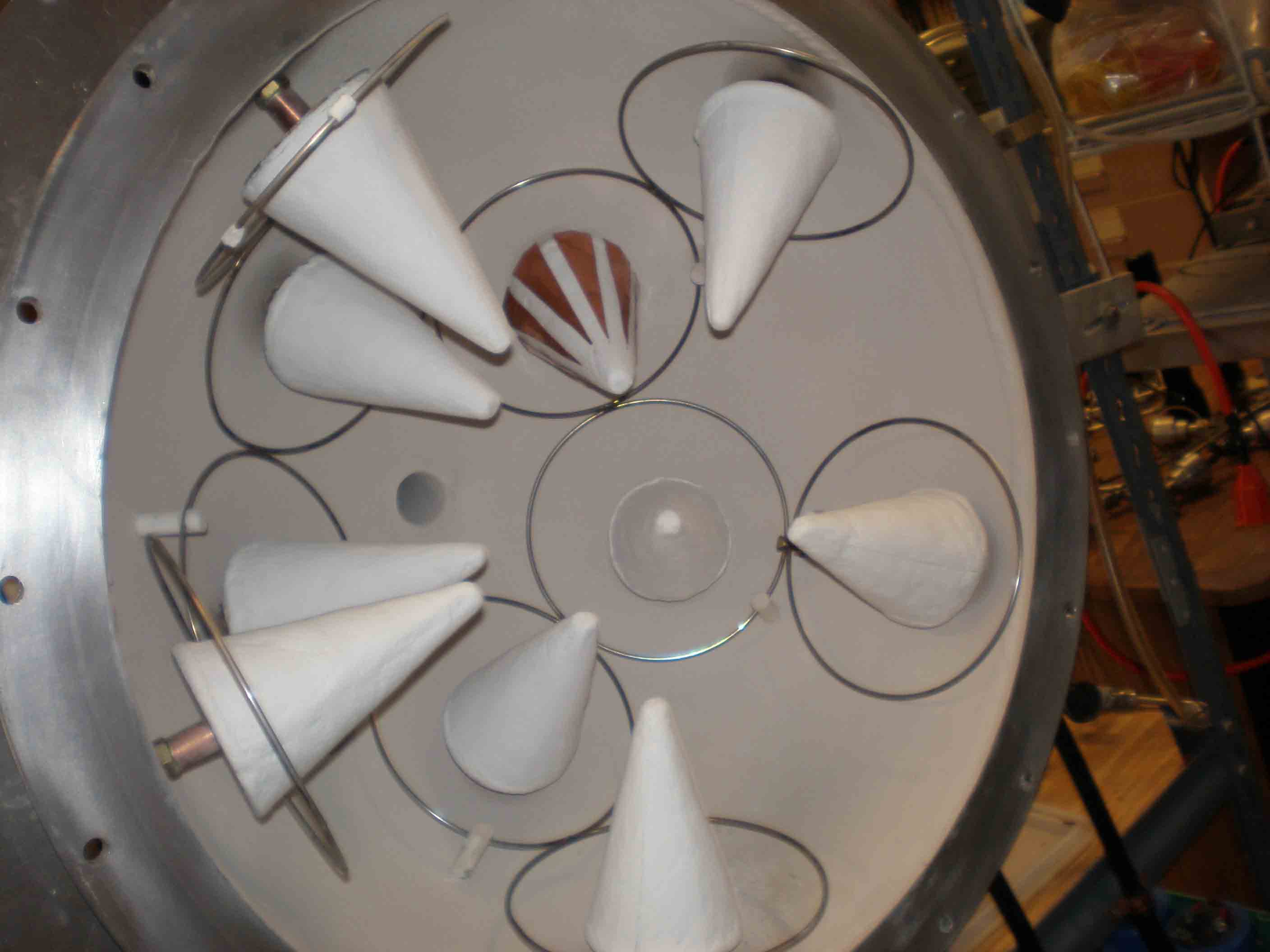
S hemisphere with grid and some antennas
|
|
|
|
 |
|
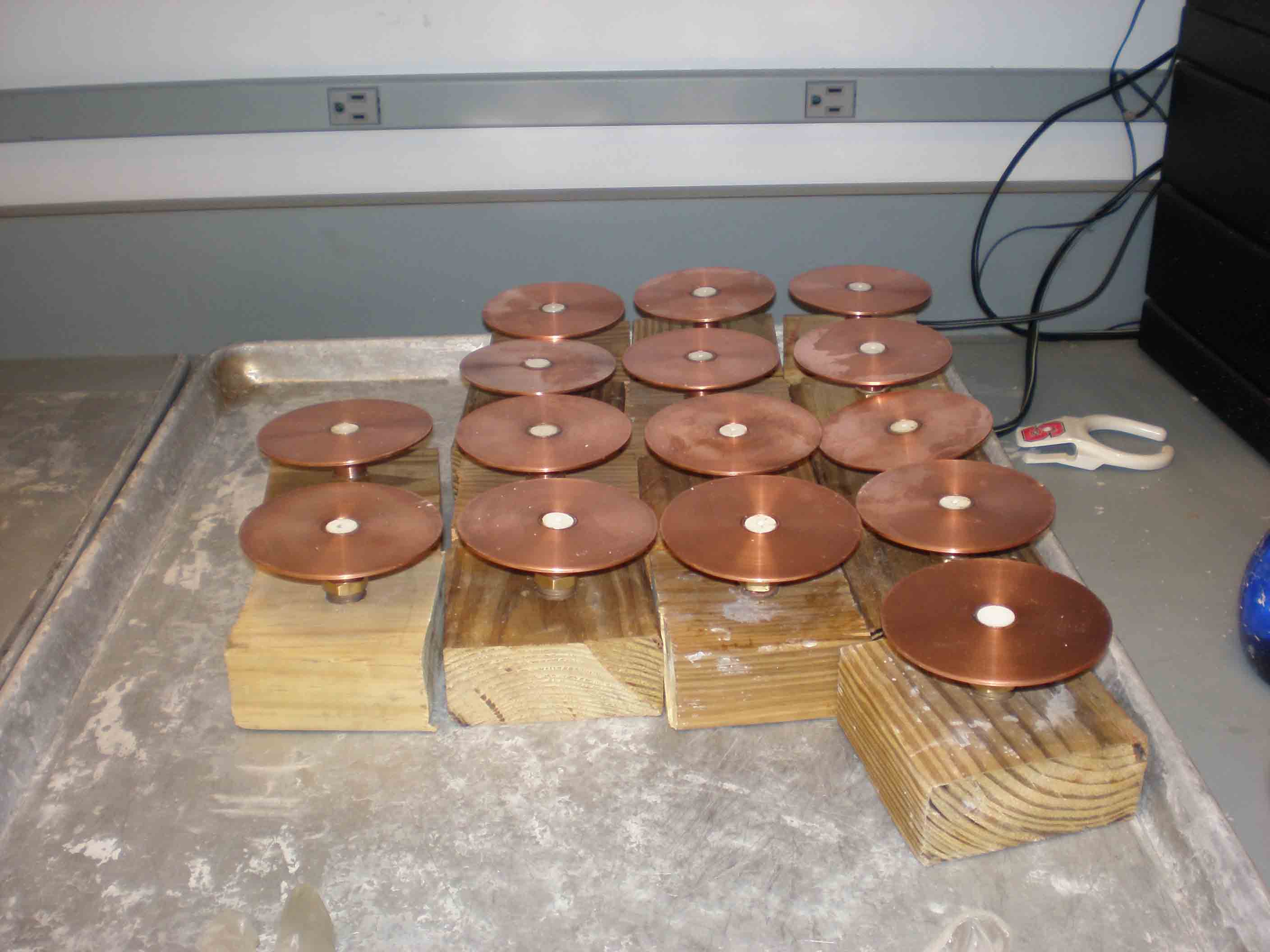
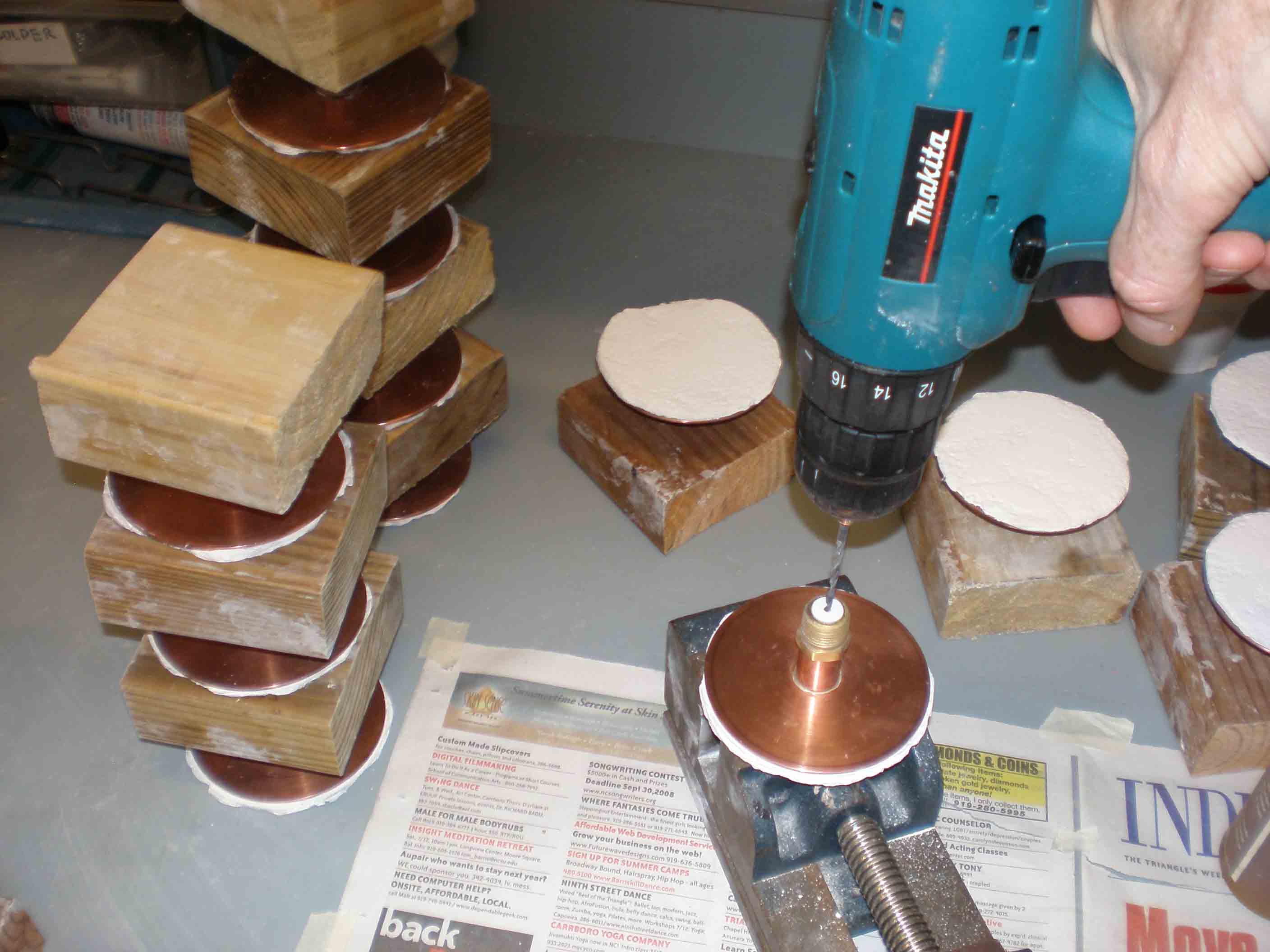
copper bases on blocks
2x4 blocks are very handy to hold the antennas
|
|
 |
|
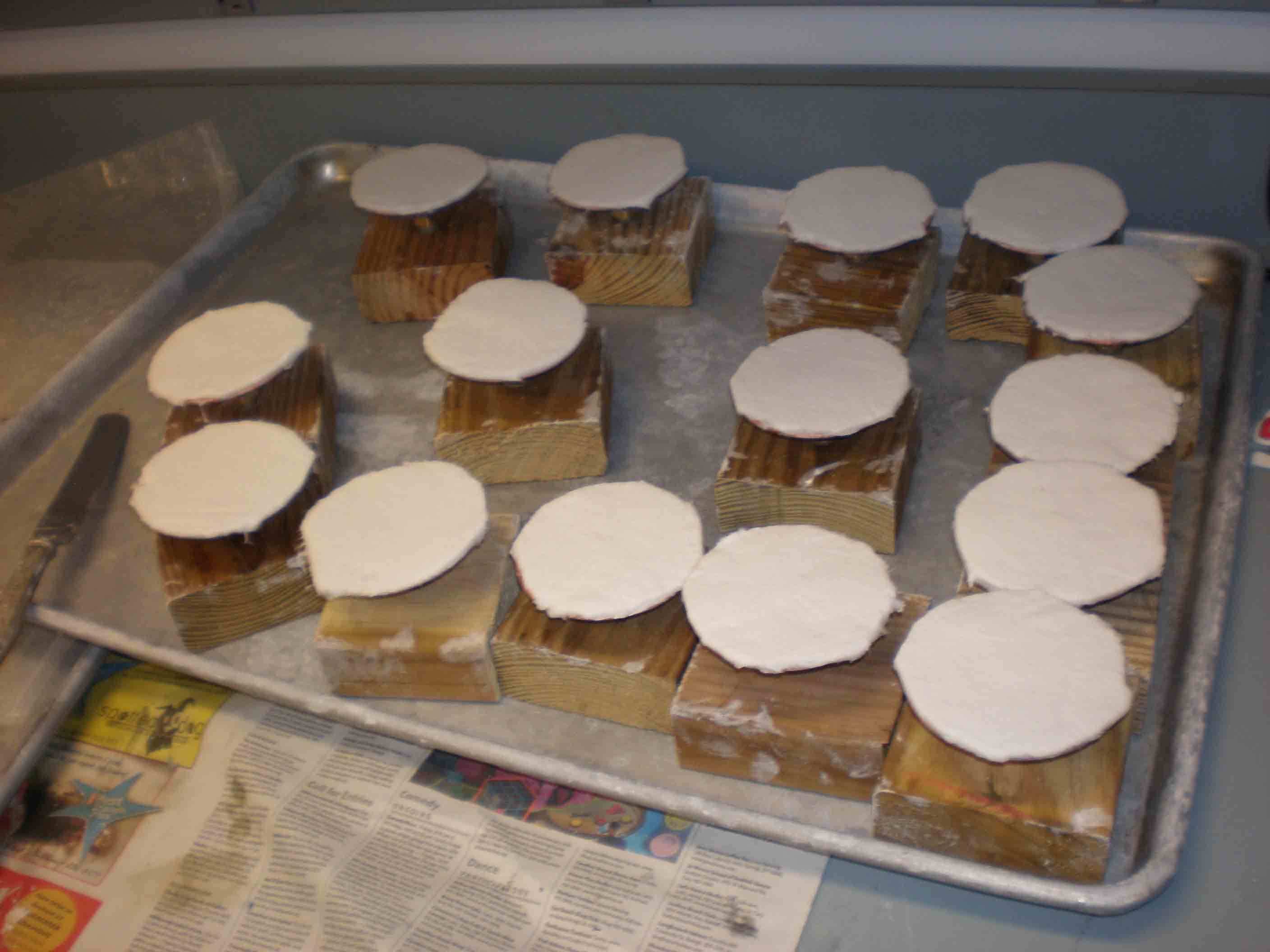
coat of ceramic composite on copper base plate
|
|
 |
|
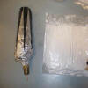
Cross-section of blown Mark 1 antenna
|
|
 |
|
drilling ceramic for 10 ga. wire
|
|
 |
|
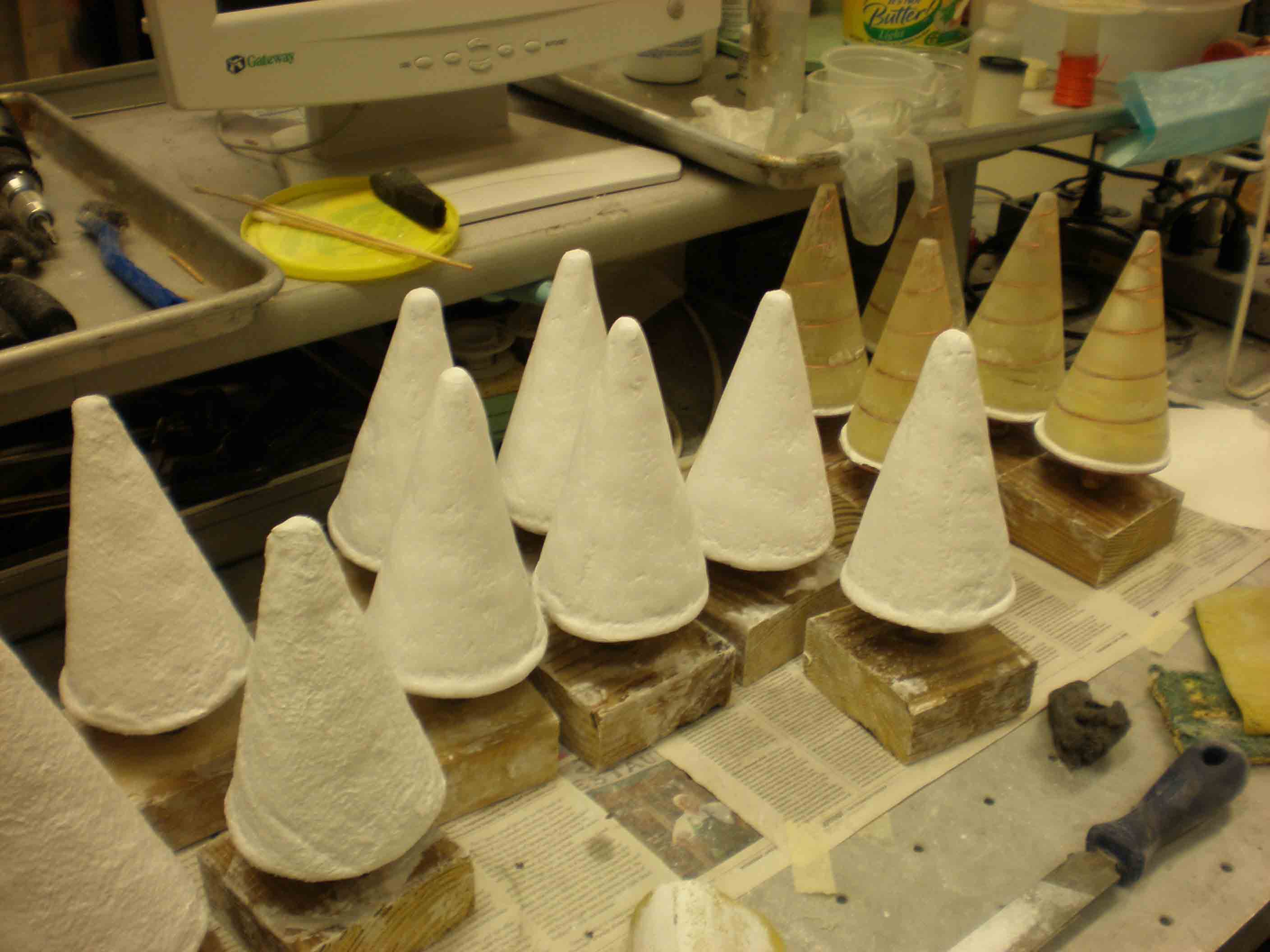
epoxy cones glued to ceramic and base
|
|
|
|
 |
|
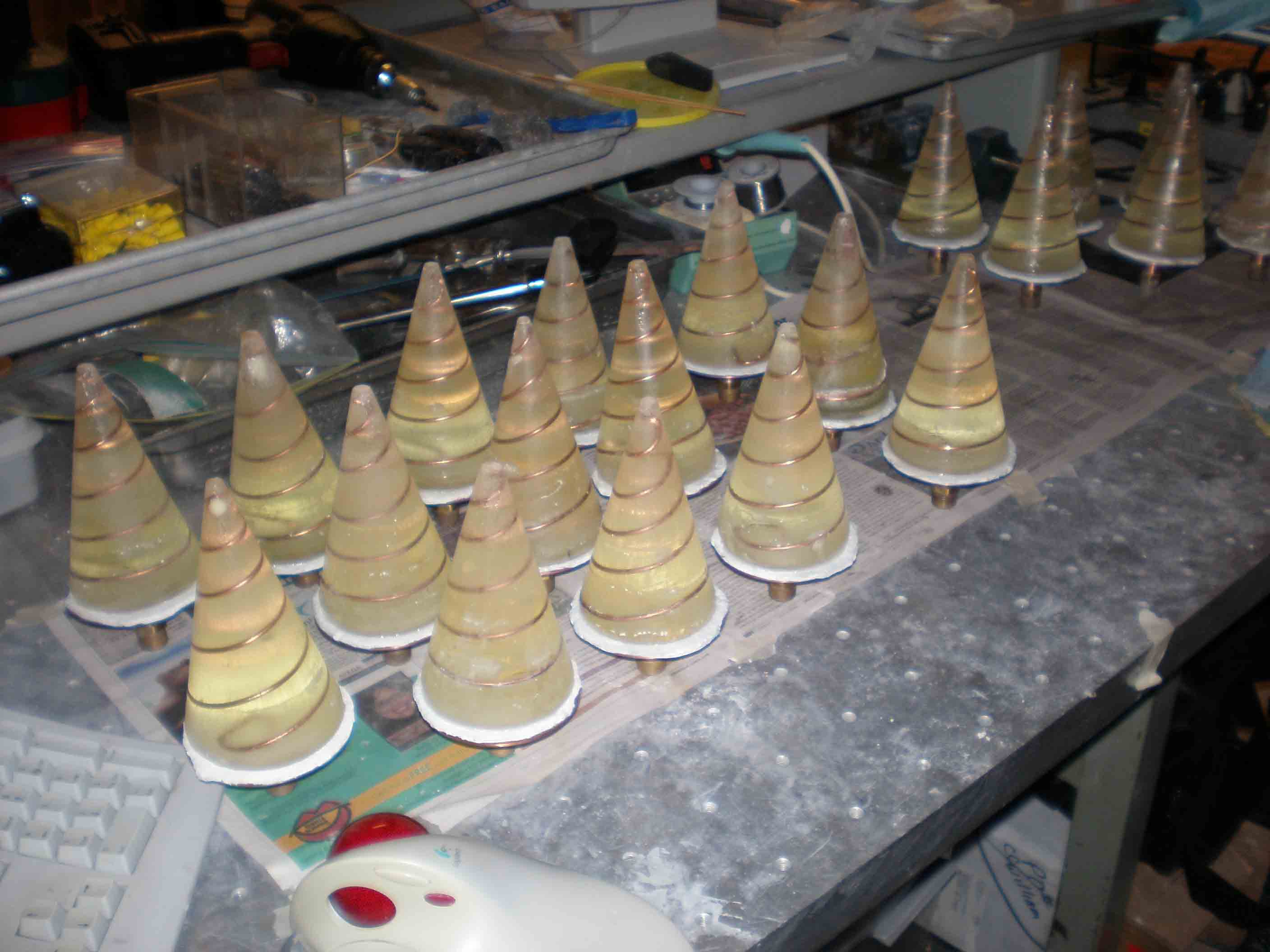
epoxy cones on bases
|
|
 |
|
ceramic composite coating over epoxy
|
|
 |
|
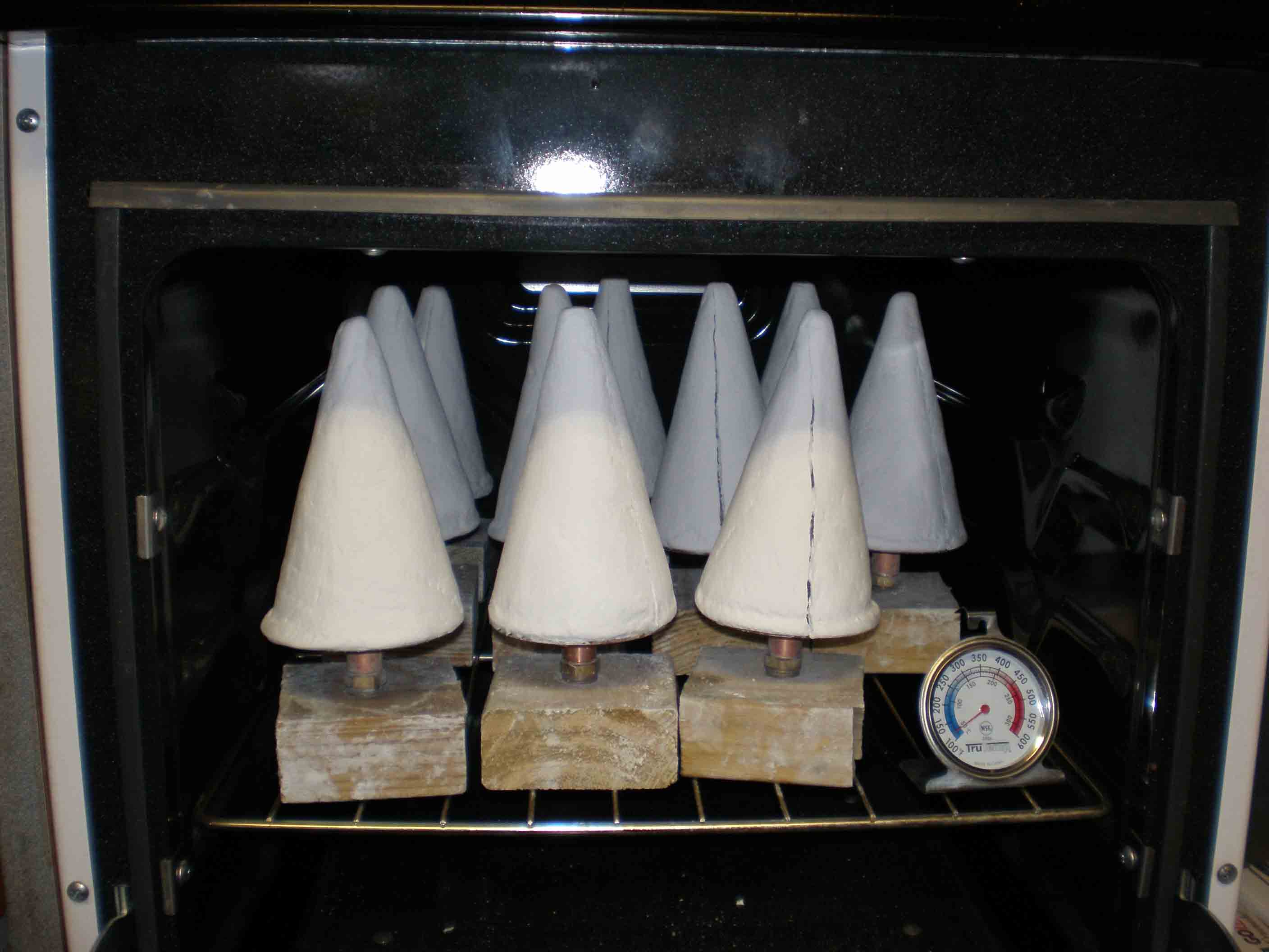
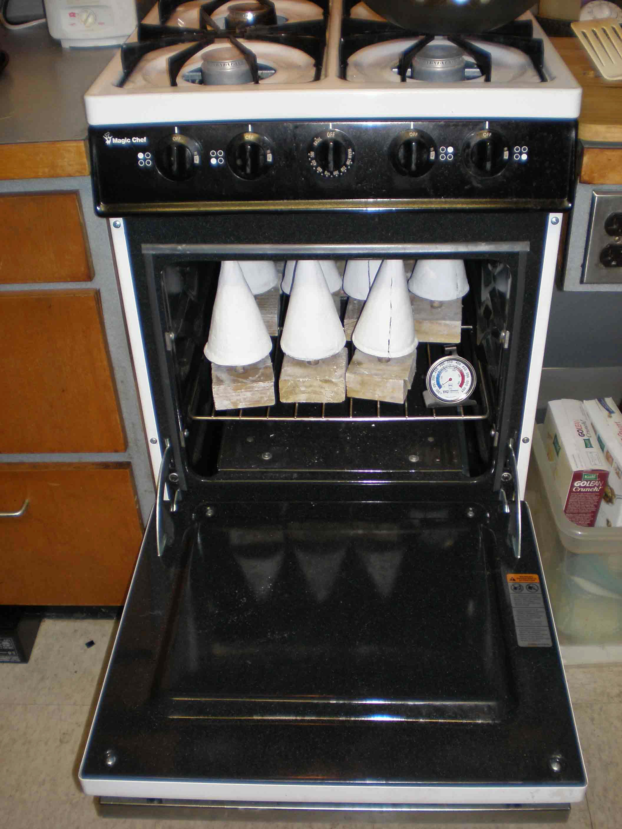
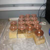
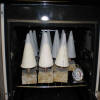
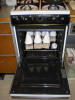
Cones at home in the oven
cured 12 hours at 140 degrees F, otherwise water still in there making the ceramic opaque to microwaves
|
|
 |
|
Cones in the oven
The only thing I've baked since moving to this apartment in 2004
|
|
 |
|
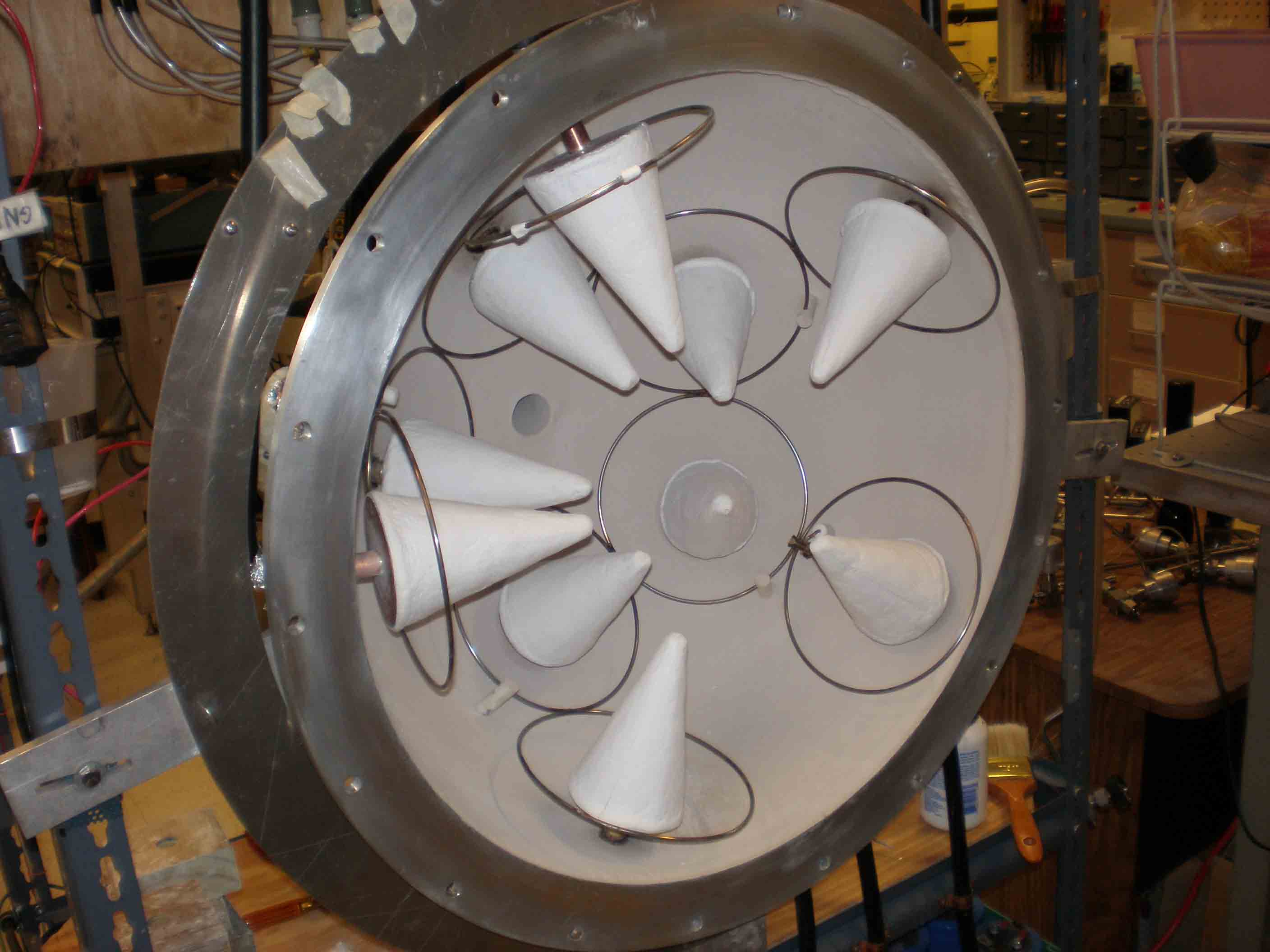
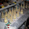
Cones set to test in S hemisphere
|
|
|
|
 |
|
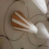
First test pattern for shield
unshielded cones fire at the base of the cone; needs shielding to match impedance and make plasma generation all along the cone
|
|
 |
|
side view of first test shield
|
|
 |
|
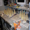
set up to test in S hemisphere
|
|
 |
|
test cone in place
|
|
 |
|
Still from video
1/2 Torr pressure, 1/500 sec shutter speed; the bright one is the trial with triangle shielding
|
|
|
|
 |
|
Still from video
1 ms shutter speed, 480 mTorr pressure, showing more detail (see unshielded antennas for comparison)
|
|
|
 Lab Pictures 7